 English
 Indonesia

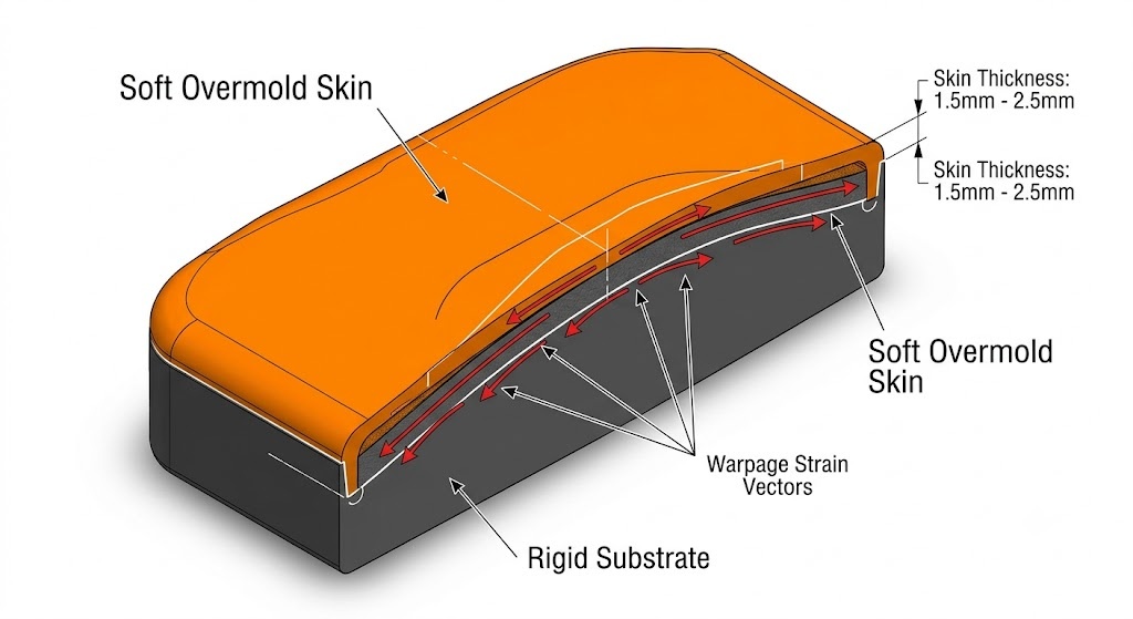
Overmolding soft-touch elastomers like Thermoplastic Elastomers (TPE) or Thermoplastic Polyurethanes (TPU) over rigid plastic, metal, or printed circuit boards (PCBs) enhances ergonomic grip, dampens vibration, and creates liquid-tight ingress protection. However, product failures—such as boundary delamination, sink marks, prolonged cooling cycles, or excessive part warpage—frequently trace back to incorrect wall thickness design.
Generic design guidelines often suggest maintaining a uniform 2.0 mm wall thickness. In practice, optimal skin thickness is heavily contingent on specific substrate materials, structural reinforcement needs, flow length ratios, and adhesion requirements. This technical guide outlines precise thickness matrices, process considerations, structural DFM rules, and validation protocols for overmolding applications.
1. Recommended Overmold (Skin) Thickness by Material and Substrate
Determining overmold thickness requires balancing functional tactile feedback against thermal stress, volumetric shrinkage, and cycle time penalties. Elastomers possess higher Coefficients of Linear Thermal Expansion (CLTE) than rigid substrates; excessively thick overmold skins exert high contractile stress during cooling, leading to substrate warpage or adhesive shearing.
The matrix below provides precise thickness boundaries across core manufacturing substrates:
| Substrate Material | Minimum Skin Thickness | Recommended Nominal Thickness | Maximum Reinforced Thickness | Primary Applications & Notes |
|---|---|---|---|---|
| Engineering Plastics (ABS, PC, PC/ABS) | 0.75 mm | 1.50 - 2.50 mm | 3.50 mm | Consumer electronics, power tool handles. Excellent chemical bonding potential via surface molecular diffusion. |
| High-Temp Polyamides (PA6, PA66, PBT) | 1.00 mm | 1.50 - 2.20 mm | 3.00 mm | Automotive engine housings, industrial sensors. Requires elevated tool temperatures to achieve full chemical adhesion. |
| Semi-Crystalline Plastics (POM, PP) | 1.20 mm | 1.80 - 2.50 mm | 3.00 mm | Low surface energy makes chemical bonding difficult; relies heavily on mechanical interlocking features. |
| Metals (Die-cast Aluminum, Zinc, Steel) | 1.00 mm | 2.00 - 3.00 mm | 4.00 mm | Surgical instruments, heavy-duty equipment grips. High thermal conductivity rapidly chills melt; requires preheating. |
| Encapsulated PCBs & Electronics | 1.00 mm | 1.50 - 2.00 mm | 2.50 mm | Low-pressure molding or delicate overmolding. Thickness must buffer delicate components against clamping pressures. |
Design Note: Soft-touch grips typically require a nominal thickness of 1.5 to 2.5 mm to achieve adequate tactile damping. Thicknesses under 1.0 mm feel rigid, while sections exceeding 3.5 mm drastically extend cooling times and introduce internal voids.
2. Minimum Injectable Skin Thickness and Thin-Wall Techniques
Achieving reliable thin-wall overmolding (under 1.0 mm) without flash, short shots, or surface hesitation marks depends on controlling flow length ratios (L/T) and melt viscosity.
When the ratio of flow length to wall thickness (L/T) exceeds 100:1, standard TPE formulations freeze prematurely. High-flow TPE/TPU formulations with a high Melt Flow Index (MFI > 25 g/10 min at 190°C/2.16kg) enable minimum wall thicknesses down to 0.50 mm - 0.75 mm over short flow paths (< 50 mm).
Key Process and Tooling Guidelines for Thin-Wall Overmolding:
- Elevated Tool Temperatures: Increase substrate mold cavity temperatures by 15°C to 25°C to prevent early freeze-off during the injection phase.
- Sequential Valve Gating or Hot Runners: Drop hot tip gates directly onto thicker sections of the overmold zone to minimize pressure drops.
- High Injection Speeds: Fill thin cavities rapidly before skin layer solidification occurs, utilizing precise multi-stage packing profiles to prevent flash.
- Venting Depth Control: Precision micro-venting (0.010 mm to 0.015 mm depth) is critical near thin edges to avoid trapped air burns without causing resin flash.
3. Design Rules for Uniform Walls, Ribs, Bosses, and Transitions
Non-uniform overmold thickness causes differential shrinkage, which creates localized stress concentrations and edge lifting. Adhering to strict geometric proportions maintains structural integrity and seamless skin-to-substrate transitions.
Geometric DFM Ratios:
- Skin-to-Core Wall Ratio: Overmold thickness should ideally match 60% to 80% of the underlying substrate wall thickness to prevent thermal distortion of the substrate during shot insertion.
- Internal Rib Thickness: Ribs embedded beneath or within the overmold skin must not exceed 50% of the main overmold nominal wall thickness. (e.g., Substrate Rib Thickness = 0.50 * Overmold Skin Thickness).
- Internal Radii (R): Avoid sharp interior corners. Provide a minimum radius of R = 0.5 mm or 0.5 to 0.75 times the wall thickness at all intersection points to minimize stress concentration factors.
- Shut-Off Step and Interlocking Grooves: Never end an overmold skin on a flush surface. Design a perimeter shut-off step with a depth equal to the full skin thickness, combined with a 0.5 mm x 0.5 mm mechanical interlocking groove to prevent peeling along exposed edges.
4. Substrate Preparation, Primers, and Bond Strength Testing
A durable overmolded part requires high interfacial adhesion strength. Adhesion mechanisms fall into two primary categories: Chemical Diffusion Bonding and Mechanical Interlocking.
Surface Pre-Treatment Methods:
- Atmospheric Plasma / Flame Treatment: Raises the surface energy of non-polar polymers (e.g., Polypropylene) above 44 dynes/cm to maximize wetting.
- Chemical Primers / Silane Coupling Agents: Applied to metal alloys or ceramic substrates prior to molding to form covalent bonds with incoming elastomeric resins.
- Abrasive Media Blasting: Creates micro-roughness on metals (Ra 2.5 - 6.3 µm), significantly improving mechanical keying.
Standard Adhesion Validation Tests:
Bond integrity is evaluated using standardized testing protocols:
- 90-Degree Peel Test (ASTM D903 / ISO 813): Quantifies the force required to peel the overmold strip from the substrate. Acceptable industrial values range from 3.5 to 8.0 N/mm depending on durometer.
- Lap Shear Testing (ASTM D1002): Evaluates shear strength under tensile loading.
Failure Mode Target: Quality control protocols require Cohesive Failure (where the elastomer material tears internally) rather than Adhesive Failure (where the skin peels off cleanly at the interface).
5. Tooling, Venting, Moldflow Simulation, and Cost Trade-Offs
Skin thickness directly influences manufacturing unit cost, cycle time, and scrap rates. Because plastic cooling time scales exponentially with wall thickness (Cooling Time is proportional to Wall Thickness squared), adding thickness carries a significant cycle time penalty.
Shrinkage Allowances & CAE Simulation:
Overmold materials exhibit volumetric shrinkage ranging from 1.2% to 2.5%, significantly higher than rigid engineered thermoplastics (0.4% - 0.7%). Tooling designers must calculate differential shrinkage in Moldflow (CAE) analysis software to ensure net-shape accuracy.
Key CAE Analysis Outputs to Evaluate:
- Volumetric Shrinkage at Freeze-out: Ensures uniform packing across thickness transitions.
- Volumetric Deflection / Warpage: Identifies if asymmetric cooling on one side of a metal or PCB substrate will induce bending forces.
- Interfacial Shear Stress: Evaluates whether injection flow pressures will displace or damage delicate substrate features or pre-placed inserts.
Get Your Overmolding DFM Review & Quote
Optimizing overmold thickness requires balancing wall uniformity, tool design, material compatibility, and tactile requirements. Our engineering team provides comprehensive DFM (Design for Manufacturability) evaluations, Moldflow thermal/warpage simulations, and rapid prototyping services.
- Turnaround Time: DFM feedback within 24 hours; prototype tooling in 5 to 7 business days.
- Compliance Standards: ISO 13485, USP Class VI medical-grade elastomers, RoHS/REACH compliant material options.
Submit your 3D CAD files (STEP/IGES) along with substrate specifications to receive a detailed thickness and manufacturability assessment from our injection molding specialists.
Frequently Asked Questions (FAQ)
1. What overmold thicknesses are recommended for common substrates like ABS, PC, aluminum, and PCBs?
Recommended nominal thicknesses are 1.5 to 2.5 mm for engineering plastics like ABS and PC, 2.0 to 3.0 mm for metals like aluminum, and 1.5 to 2.0 mm for encapsulated PCBs to ensure proper protection without applying excessive thermal stress to sensitive electronics.
2. What is the minimum practical overmold thickness achievable with TPE, and what process changes enable it?
The minimum practical thickness is 0.50 to 0.75 mm using high-flow TPE/TPU formulations. Achieving this requires elevated mold cavity temperatures, high injection speeds, sequential valve gating, and precision micro-venting to prevent premature freezing.
3. How do I design for uniform wall thickness and avoid sink marks or delamination?
Keep the overmold thickness between 60% and 80% of the underlying substrate wall, design internal ribs at no more than 50% of the main overmold wall, include generous transition radii (minimum 0.5 mm), and incorporate perimeter shut-off steps with mechanical locking grooves.
4. How should I prepare a substrate to maximize bond strength for overmolding?
Substrates can be prepared using atmospheric plasma or flame treatment to increase surface energy, applying silane coupling primers for metals, or media blasting to create mechanical surface roughness. Aim for cohesive failure during ASTM D903 peel testing.
5. How does overmold thickness impact cooling time and overall part cost?
Cooling time increases exponentially with the square of wall thickness. Increasing skin thickness from 1.5 mm to 3.0 mm can more than double the required cooling cycle time, significantly increasing per-unit manufacturing costs.
6. What causes overmold peeling along sharp edges, and how does geometry prevent it?
Peeling occurs when shear forces act on exposed flush edges with weak mechanical anchorage. Designing a defined shut-off step along the parting line combined with an undercut or mechanical retention groove anchors the edge and prevents peeling under mechanical abrasion.


