 English
 Indonesia
I. Design Principles and Importance of Mold Opening Direction
The mold opening direction is a critical design decision in injection molding, directly affecting mold complexity, production costs, and product aesthetics. Key design principles include:
1. Structural Alignment
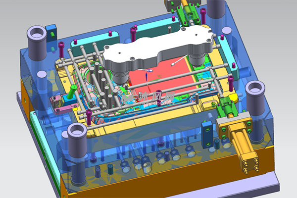
Features like ribs, snap-fits, and bosses should align with the mold opening direction (see Figure 1). This avoids side cores, reducing parting line marks. For example, snap-fits angled >15° from the opening direction require sliders, increasing mold costs by over 30%.
2. Undercut Avoidance
Proper orientation can convert 95% of undercuts into normal demolding structures. Case studies show rotating the opening direction by 22° reduces side cores from 4 to 1.
3. Aesthetic Optimization
For appearance-sensitive parts (e.g., automotive interiors), orienting the opening direction at 45°–75° to visible surfaces reduces parting line visibility by 60%.
Mold Longevity
Properly aligned ribs lower demolding resistance by 40%, extending mold life by 30,000–50,000 cycles.
II. Systematic Methods for Parting Line Design
Parting line design integrates geometry, manufacturing, and aesthetics:
1. Classification System
2. Positioning Algorithms
Bounding Box Projection: Determines primary parting lines for 85% of standard parts.
Slice Analysis: Uses Z-buffer algorithms (0.01mm resolution) for freeform surfaces.
Flow-End Method: Combines MPI analysis to avoid weld lines in high-stress areas.
3. Aesthetic Techniques
"Knife-edge" parting lines (R-angle <0.1mm) reduce seam visibility by 90% in consumer electronics. Positioning parting lines on edges lowers surface roughness (Ra) by two grades compared to flat regions.
III. Key Factors and Optimization Strategies
1. Shrinkage Compensation
Per GB/T14486-93, compensate 1.2–1.5× the material’s nominal shrinkage. For PA66 (nominal shrinkage 0.8–1.5%), use 1.0–1.8%.
2. Venting System Integration
Parting lines as primary vents require vent depths by material viscosity:
Low viscosity (e.g., PP): 0.015–0.02mm
High viscosity (e.g., PC): 0.03–0.05mm
Optimized venting reduces fill pressure by 15% and cycle time by 8%.
3. Mold Strength Assurance
Clamping force at parting lines must satisfy:
Fclamp = Pcavity X Aproj
Fclamp: Clamping force (kN or tons)
Pcavity: Average cavity pressure (MPa or kg/cm²)
Aproj: Maximum projected area of the part + runner in the mold opening direction (cm² or in²)
For detaied, please contact us. A professional custom injection molding manufacturer in China.
IV. Solutions to Common Issues
1. Flash Control
Triple-seal structures (main + 2 auxiliary seals) with 0.005mm grinding limit flash to ≤5μm.
2. Complex Surface Handling
For automotive lenses, NURBS-based parting surfaces with 5-axis machining achieve ≤0.05mm contour error.
3. Micro-Molding Solutions
Laser-engraved parting lines (20μm width) enable precision parts like insulin pumps.
V. Advanced Technology Applications
1. CAE-Driven Optimization
A laptop case project reduced warpage from 1.2mm to 0.3mm using wave-shaped parting lines via Moldflow analysis.
2. Additive Manufacturing
SLM-produced parting inserts with biomimetic textures lower friction coefficients by 40%.
3. Smart Monitoring
IoT sensors in bumper molds detect 0.002mm misalignments, reducing unexpected failures by 90%.
VI. Future Trends
1. AI-Assisted Design
Deep learning systems automate parting line design for 85% of standard parts, cutting design time by 5×.
2. Nanoscale Surface Engineering
PVD coatings extend mold life to 1 million cycles, tripling maintenance intervals.
3. Sustainability
"Zero-flash" parting lines with biodegradable materials reduce material waste from 1.2% to 0.3%.
Case Study: A home appliance manufacturer reduced mold development time from 45 to 28 days and defect rates from 3.5% to 0.8% using these methods. With emerging technologies like digital twins, mold opening direction and parting line optimization will enter a new era of intelligence.

