 English
 Indonesia


Injection mold life is often reduced to a single number during quotation: 100,000 cycles, 500,000 cycles or more than one million cycles. In reality, that number is only meaningful when it is connected to the mold steel, resin, part geometry, production conditions, maintenance strategy and quality requirements of the project.
A mold does not suddenly fail at cycle 100,001 or 1,000,001. Tool life normally declines gradually. Gates wear, shutoffs loosen, ejector bores enlarge, textures deteriorate and dimensions begin to drift. The more useful definition of mold life is therefore the period during which the tool can continue producing acceptable parts within agreed dimensional, cosmetic and functional requirements.
What Does 100,000-Cycle or 1-Million-Cycle Mold Life Actually Mean?
Mold life should be treated as an engineering target rather than a universal guarantee. Two tools manufactured from the same steel can have very different service lives if one runs an unfilled polypropylene and the other processes a high-glass-content engineering resin.
During production, several types of deterioration may define the end of useful tool life:
- excessive flash at worn parting lines or shutoffs;
- dimensional drift outside the approved tolerance window;
- gate erosion that changes filling or vestige size;
- ejector wear that creates marks, sticking or instability;
- slide or lifter wear that affects alignment;
- surface deterioration that no longer meets cosmetic requirements;
- cooling-system degradation that increases cycle time or warpage;
- frequent repair requirements that make production uneconomical.
A mold may still open, close and produce parts after these conditions appear, but it may no longer be considered production-capable if the parts fail inspection or maintenance becomes excessive.
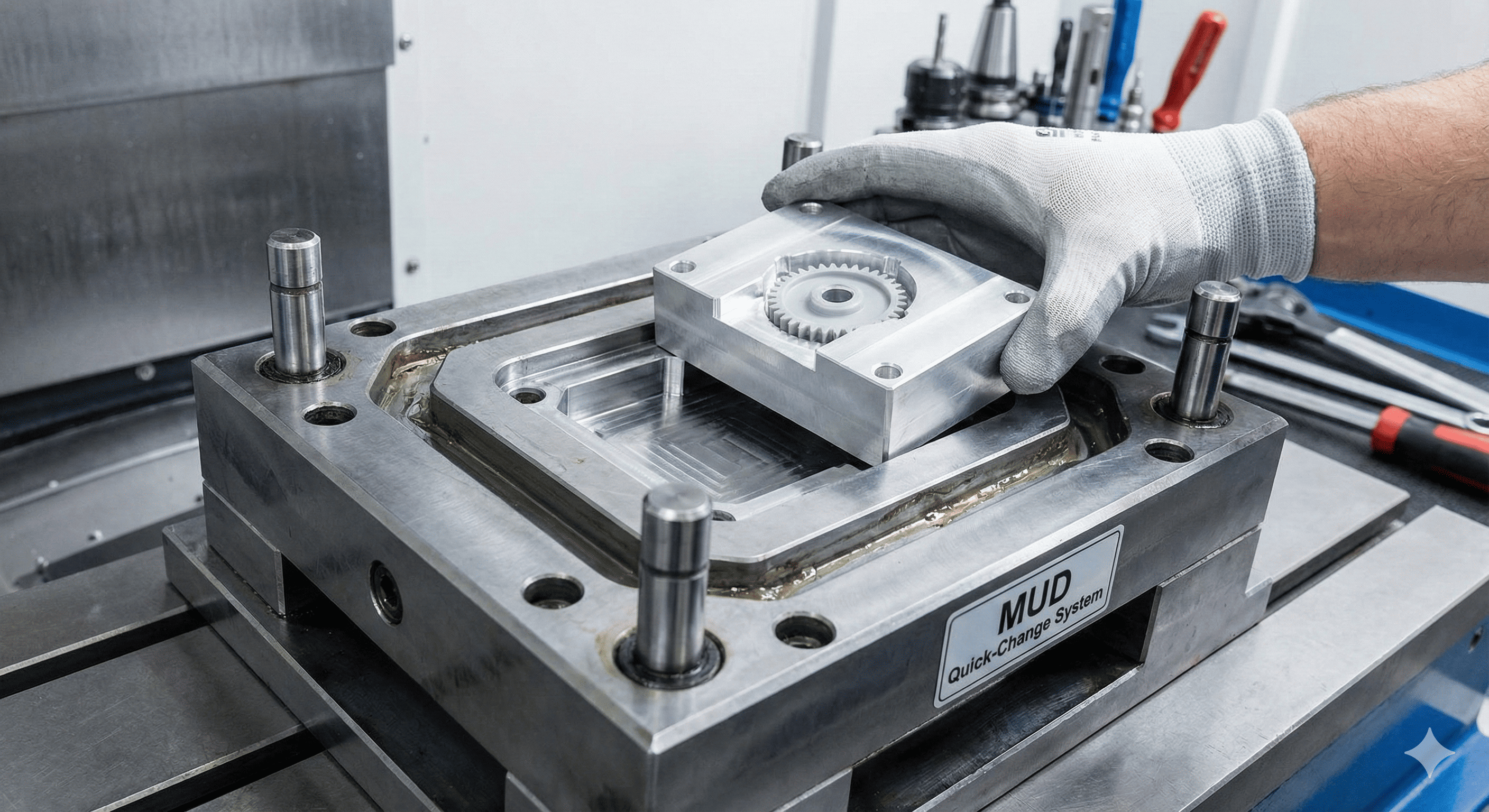
Mold Steel and Hardness Set the Starting Point
Tooling material is one of the first variables that affects expected mold life. Softer materials can be faster and less expensive to machine, while harder steels generally provide greater resistance to abrasion, deformation and repeated contact.
| Tooling Direction | Typical Strength | Typical Use |
| Aluminum tooling | Fast machining and strong thermal conductivity | Prototype and lower-volume programs |
| Pre-hardened mold steel | Balanced machinability and durability | Bridge and medium-volume production |
| Hardened production steel | Higher wear resistance and long-term stability | High-cycle and demanding production |
| Corrosion-resistant mold steel | Improved resistance to moisture and aggressive materials | Medical, optical, corrosive or high-cleanliness applications |
However, harder is not automatically better. Higher hardness can increase machining time, polishing difficulty, tooling cost and repair complexity. Some highly hardened materials can also become less forgiving when local stress concentration is poorly controlled.
The correct approach is to identify where wear and mechanical loading will occur, then select the steel, hardness and insert strategy around those areas.
The Resin Can Shorten Mold Life Faster Than Buyers Expect
The material being molded is one of the most important variables in tool life. A mold running unfilled PP faces a very different wear environment from one processing PA66 GF50 or PPS with heavy glass reinforcement.
Abrasive Engineering Plastics
Glass fibers and mineral fillers increase stiffness and heat resistance in the finished part, but they also increase abrasion inside the mold. High-wear areas often include:
- gates and gate inserts;
- runner intersections;
- thin cores;
- shutoff surfaces;
- cavity edges exposed to high melt velocity;
- valve pins and hot runner nozzle areas.
For glass-filled PA66, PBT, PPS and similar compounds, local wear protection may be more important than simply specifying a stronger mold base.
Corrosive and Deposit-Forming Materials
Certain flame-retardant systems, PVC-type materials and additives can create corrosion, deposits or surface deterioration. If these materials are expected, corrosion-resistant steel, coatings and a disciplined cleaning strategy may be required.
High-Temperature Resins
Materials such as PPS, PEEK, PEI and high-temperature nylons place additional demands on mold temperature control, hot runner components, seals and repeated thermal cycling.
For this reason, mold life should always be discussed against the exact resin grade, not just the geometry of the part.
Mold Design Often Determines Where the Tool Fails First
Two molds can use the same steel and still have very different service lives because wear is rarely distributed evenly across the entire tool.
Thin Cores
Long or narrow cores may deflect under injection pressure and can become vulnerable to fatigue, wear or breakage over long production runs.
Shutoff Surfaces
Angled and sliding shutoffs experience repeated contact. Poor alignment or insufficient hardness can quickly create flash and dimensional loss.
Slides and Lifters
Guide systems, wear plates, lubrication and preload determine whether moving components remain stable over hundreds of thousands of cycles.
Ejector Systems
Ejector pins and bores are repeated wear interfaces. Misalignment, poor lubrication or excessive ejection load can reduce their service life.
Gate Areas
High shear and high melt velocity make gate regions common wear points, especially with filled engineering plastics.
Parting Lines
Repeated clamping and contamination can damage the sealing surfaces that prevent flash.
This is why a one-million-cycle mold should be designed as a one-million-cycle mold from the beginning. Simply replacing standard steel with a harder steel does not automatically convert a basic mold into long-life production tooling.
Replaceable Wear Components Are a Major Feature of Long-Life Molds
High-life tooling is not designed on the assumption that nothing will ever wear. Instead, predictable wear is localized into components that can be serviced or replaced without rebuilding the entire mold.
Typical serviceable elements include:
- replaceable gate inserts;
- hardened shutoff inserts;
- slide wear plates;
- replaceable thin cores;
- ejector bushings;
- replaceable cavity inserts;
- hot runner tips, heaters and valve components.
Designing wear components into the mold increases initial engineering effort, but it can significantly reduce downtime and repair cost during long production programs.
Process Settings Can Destroy a Good Mold
Tool life is not controlled by mold design alone. A high-quality mold can wear prematurely if it operates under unnecessary pressure, excessive clamp force or poor machine alignment.
Excessive Injection Pressure
Higher pressure increases loading on cavity surfaces, cores, shutoffs and parting lines. If high pressure is being used to compensate for a poor gate, restricted venting or an undersized flow path, the process may be adding unnecessary stress to the tool.
Excessive Clamp Force
More clamping force is not always better. Excessive force can increase long-term loading on mold plates, parting surfaces and machine-mold interfaces.
Poor Alignment
Poor platen alignment or repeated off-center loading can accelerate wear on leader pins, bushings, slides and shutoffs.
Inconsistent Mold Temperature
Unstable thermal conditions increase expansion and contraction, alter dimensions and can create additional mechanical stress during production.
Tool life is therefore partly a tooling problem and partly a production-discipline problem.
Cooling-System Condition Also Affects Mold Life
Cooling systems are often discussed only in relation to cycle time, but their condition also influences long-term mold stability.
Over time, cooling channels can develop:
- scale;
- corrosion;
- restricted flow;
- uneven temperature distribution;
- leaks or seal degradation.
If one section of the mold begins running hotter, the process may develop longer cycles, increased warpage or inconsistent dimensions. Operators may respond by increasing packing pressure or changing molding conditions, which can indirectly increase stress on the tool.
For high-cycle molds, cooling-system serviceability, water quality and flow monitoring should therefore be considered part of the mold-life strategy.
Preventive Maintenance Turns Potential Tool Life Into Real Tool Life
A mold designed for long service will not achieve its potential if it is only repaired after defects appear.
Preventive maintenance should be based on actual production conditions and shot count rather than calendar time alone.
| Maintenance Level | Typical Checks |
| Every production run | Clean cavity/core, inspect parting line, check contamination, review molded-part quality |
| Periodic maintenance | Lubricate slides and lifters, inspect gates, ejectors, guide components and hot runner connections |
| Major maintenance | Disassemble wear components, inspect dimensional wear, clean cooling channels, replace seals and refurbish inserts |
Shot counters are particularly useful because a tool that runs 200,000 cycles in three months should not follow the same maintenance schedule as a similar mold that runs 20,000 cycles in a year.
Maintenance frequency should also become more conservative when the mold processes abrasive or high-temperature resins.
100,000 vs 1 Million Cycles: What Changes in the Tooling Strategy?
The difference between a lower-volume tool and a million-cycle production tool should be visible in construction, serviceability and maintenance planning.
| Design Factor | Approx. 100k-Cycle Strategy | 1M+ Cycle Strategy |
| Tooling material | Pre-hardened steel may be sufficient | Hardened production steel typically considered |
| Wear inserts | Selective | Designed into critical wear areas |
| Gate area | Standard construction may be sufficient | Replaceable hardened inserts often preferred |
| Slides and lifters | Standard wear solution | Greater emphasis on hardened wear plates and serviceability |
| Ejector system | Standard production design | Higher durability and planned replacement of wear components |
| Cooling system | Optimized for production | Optimized for production and long-term serviceability |
| Alignment | Standard precision requirements | Higher focus on long-term wear control |
| Maintenance plan | Basic scheduled maintenance | Defined cycle-based preventive maintenance |
| Spare parts | Limited | Planned spare wear components |
These differences are illustrative. Actual mold construction should be determined by the specific resin, geometry, tolerances, cavity count and production environment.
One Million Parts Does Not Mean One Million Mold Cycles
This is one of the most common mistakes in mold-life planning.
The required number of tool cycles depends on cavity count.
If the lifetime requirement is 2,000,000 parts and the mold has four cavities:
The mold should then include additional allowance for:
- mold trials;
- process setup;
- startup scrap;
- quality rejects;
- engineering trials;
- production buffer.
Likewise, an eight-cavity mold producing one million parts theoretically requires only 125,000 productive shots before allowances are added.
This is why the required tool life should be calculated from both lifetime volume and cavity count before a mold specification is finalized.
Why the Cheapest Mold Can Become the Most Expensive
The lowest mold quotation does not always produce the lowest tooling cost over the full product lifecycle.
Consider two simplified options:
| Item | Tool A | Tool B |
| Initial investment | $35,000 | $75,000 |
| Illustrative mold-life target | 150,000 cycles | 1,000,000 cycles |
| Best fit | Shorter production program | Long-term production program |
If the project only requires 100,000 cycles, Tool A may be the better commercial decision. If the project requires 800,000 cycles, repeated repair, refurbishment or replacement may make Tool B more economical.
The objective is not to maximize mold life at any cost. It is to match mold life to the commercial life of the product.
What Buyers Should Specify When Requesting Mold Life
Instead of asking a mold supplier for a generic “one-million-shot mold,” buyers should provide the production information needed to engineer the tool correctly.
- Expected annual production volume
- Expected lifetime part demand
- Planned cavity count
- Exact resin grade
- Glass-fiber or mineral-filler percentage
- Target cycle time
- Critical dimensions and tolerances
- Surface or texture requirements
- Production location
- Hot runner requirements
- Expected maintenance capability
- Required spare parts
- Target mold life
The mold supplier should then be able to explain:
- recommended steel grades;
- target hardness;
- replaceable insert strategy;
- expected wear locations;
- maintenance requirements;
- recommended spare components.
Design Mold Life Around the Program, Not Around a Marketing Number
A 100,000-cycle mold and a one-million-cycle mold should not simply be two versions of the same tool with different steel hardness. Long-life tooling requires more attention to wear localization, serviceability, alignment, cooling, moving components and preventive maintenance.
At the same time, not every product needs a million-cycle mold. Overengineering tooling for an uncertain or short product program can tie up unnecessary capital, just as under-specifying a high-volume tool can create expensive downtime later.
The correct mold-life target is the one that matches lifetime part demand, cavity count, resin severity and production risk.
Need a Mold Designed for 100,000, 500,000 or 1 Million+ Cycles?
IMTEC Mould supports mold design and manufacturing, injection molding, insert overmolding and engineering co-development for prototype, bridge and long-term production programs.
Our engineering team can review your expected lifetime volume, cavity count, resin grade, critical dimensions and production requirements to recommend an appropriate tooling construction and mold-life target.
Send your CAD files, resin specification, annual quantity, lifetime quantity and target cycle time for a tooling-life and mold-construction review.
Discuss Your Mold-Life RequirementFrequently Asked Questions
How many cycles should an injection mold last?
There is no universal number. Mold life depends on tool material, resin, geometry, cavity count, process conditions, wear areas and maintenance. The correct target should be matched to the expected production program.
What is the difference between a 100,000-cycle and a 1-million-cycle mold?
A longer-life mold usually places more emphasis on hardened tooling materials, replaceable wear inserts, alignment, serviceability, cooling-system durability and cycle-based preventive maintenance.
Does harder mold steel always mean longer mold life?
No. Hardness improves wear resistance, but poor geometry, weak shutoff design, bad alignment or incorrect processing can still cause premature failure. Tool steel should be selected as part of the complete mold design.
How much does glass-filled resin reduce mold life?
There is no fixed percentage. The impact depends on glass content, melt velocity, gate design, tool steel, coatings and production conditions. High-filled materials generally require greater attention to wear protection.
Can a lower-life mold be upgraded later for higher production?
Sometimes, but the upgrade potential depends on the original construction. Hardened inserts, replacement cores or wear plates may extend service life, but a basic mold may not be economically convertible into true long-life production tooling.
How do I calculate mold-life requirements for a multi-cavity mold?
Divide lifetime part demand by the number of cavities, then add allowance for trials, setup scrap, rejects and production buffer. For example, one million parts from an eight-cavity mold require approximately 125,000 productive cycles before additional allowances.


