 English
 Indonesia
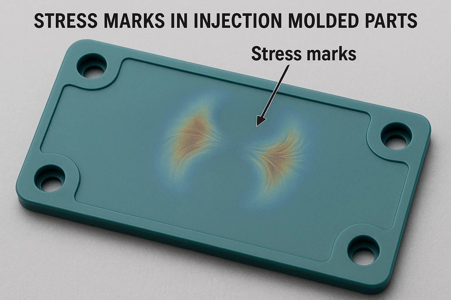
I. Definition and Manifestations of Stress Marks
Stress marks in injection molded parts are surface defects caused by localized stress concentration, appearing as glossy or uneven texture. Common locations include:
- Visual Discrepancies: More noticeable on dark-colored parts, resembling "ghost lines" or uneven shading.
- Positional Features: Often occur near flow ends, weld lines, and areas with uneven cooling.
II. Root Cause Analysis
1. Mold Design Flaws
- Improper Gate Design: Small gates or poor placement lead to high shear rates and temperature gradients.
- Abrupt Wall Thickness Changes: Thickness variations exceeding 30% cause uneven shrinkage (e.g., thin-walled areas restrict contraction, generating tensile stress).
- Inadequate Venting: Gas traps at parting lines or flow ends create localized overheating and flow turbulence.
- Sharp Corners and Rib Design: High flow resistance at sharp angles; ribs thicker than 40%-60% of the main wall thickness disrupt cooling uniformity.
2. Process Parameter Issues
- Excessive Injection Speed/Pressure: High shear stress and molecular orientation increase residual stress.
- Temperature Mismanagement: Low melt temperature or uneven mold cooling (e.g., poorly designed cooling channels) amplifies shrinkage differences.
- Insufficient Packing Pressure: Short packing time or low pressure fails to compensate for shrinkage, causing sink marks and stress marks in thick sections.
3. Material Characteristics
- High Melt Flow Index (MFI): Excessively fluid materials promote molecular orientation and uneven shrinkage.
- Crystallinity Effects: Crystalline materials (e.g., PP, PA) are sensitive to cooling rates; thick-wall areas develop crystallinity disparities.
- Additive Segregation: Fillers like glass fibers accumulate at flow ends, weakening interfacial bonding.
4. Product Design Limitations
- Non-Uniform Wall Thickness: Examples include laptop back covers with 40%-60% thickness variations.
- Poor Weld Line Placement: Stress marks form when weld lines coincide with cosmetic surfaces.
III. Comprehensive Solutions
1. Mold Design Optimization
- Gate Modifications: Enlarge gates (e.g., 1.5mm → 2.0mm); adopt fan or overlap gates to reduce shear.
- Gradual Thickness Transitions: Add radii (≥0.5× wall thickness) at abrupt changes; case studies show 80% stress mark reduction.
- Enhanced Venting: Add vent slots (0.02-0.04mm depth) at flow ends; use porous steel or insert vents.
- Conformal Cooling: Implement conformal cooling channels to limit temperature variation to ±5°C.
2. Process Adjustments
- Temperature Control: Raise melt temperature by 10-20°C (e.g., PA66: 270°C → 290°C) and mold temperature by 20-30°C (e.g., ABS: 60°C → 80°C).
- Multi-Stage Injection: Start with low speed (30%-50% max) for initial filling, then switch to high speed; set packing pressure at 70%-90% injection pressure.
- Extended Packing Time: Increase from 2s to 4s to mitigate shrinkage and residual stress.
3. Material Modifications
- Low-Shrinkage Materials: Add 30% talc to PP, reducing shrinkage from 1.8% to 0.8%.
- Flow Additives: 0.1%-0.5% silicone-based lubricants lower melt viscosity by 10%-20%.
- Fiber Compatibility: Treat glass fibers with coupling agents to minimize interfacial stress.
4. Post-Processing & Testing
- Annealing: PC parts annealed at 120°C for 2 hours eliminate 60%-80% internal stress.
- Stress Detection: Use polarized light or solvent immersion (e.g., ABS in glacial acetic acid for 2 minutes) for qualitative analysis.
IV. Case Studies
Case 1: Toy Gun Stock Stress Marks
- Issue: PP+10%GF part showed stress marks on ribs (50% thickness difference).
- Fix: Reduce rib thickness to 40% of main wall; add radii; lower packing pressure (80MPa → 60MPa); raise mold temp (60°C → 80°C).
- Result: 100% elimination; yield increased from 70% to 95%.
Case 2: Laptop Cover Stress Marks
- Issue: PC+ABS part had stress marks due to 0.9mm/1.5mm wall mismatch.
- Fix: Reposition gate to fill thick areas first; raise mold temp (90°C → 110°C); extend packing to 6s.
- Result: 90% reduction; 98% cosmetic pass rate.
V. Summary
Stress mark mitigation requires multidisciplinary optimization:
- Preventive Design: Limit wall thickness variation (≤20%); use radii and balanced runners.
- Precision Processing: Gradient temperature/pressure control with adequate packing.
- Material Selection: Prioritize low-shrinkage, high-flow materials; use modifiers as needed.
Systematic improvements enhance aesthetics, mechanical performance, and cost efficiency.

