 English
 Indonesia
Summary
Flame-retardant (FR) polymer grades are specified across automotive, electronics, electrical, and construction applications — but they introduce processing challenges and tooling risks that standard grades do not. FR additives narrow process windows, increase corrosiveness to mould steel, affect surface finish, and complicate recycling streams. This guide covers the UL94 rating system in detail, explains how each major FR chemistry interacts with injection moulding equipment and tooling, and provides practical specifications for mould design and steel selection when running FR materials.
1. Why Flame Retardancy Matters in Injection Moulding
Plastics burn. Most engineering thermoplastics — ABS, PP, PA, PC — are inherently combustible, with limiting oxygen indices (LOI) of 17–28%. In applications where ignition risk exists — electrical enclosures, EV battery housings, consumer electronics, aircraft interiors, building panels — unmodified polymers cannot meet fire safety regulations.
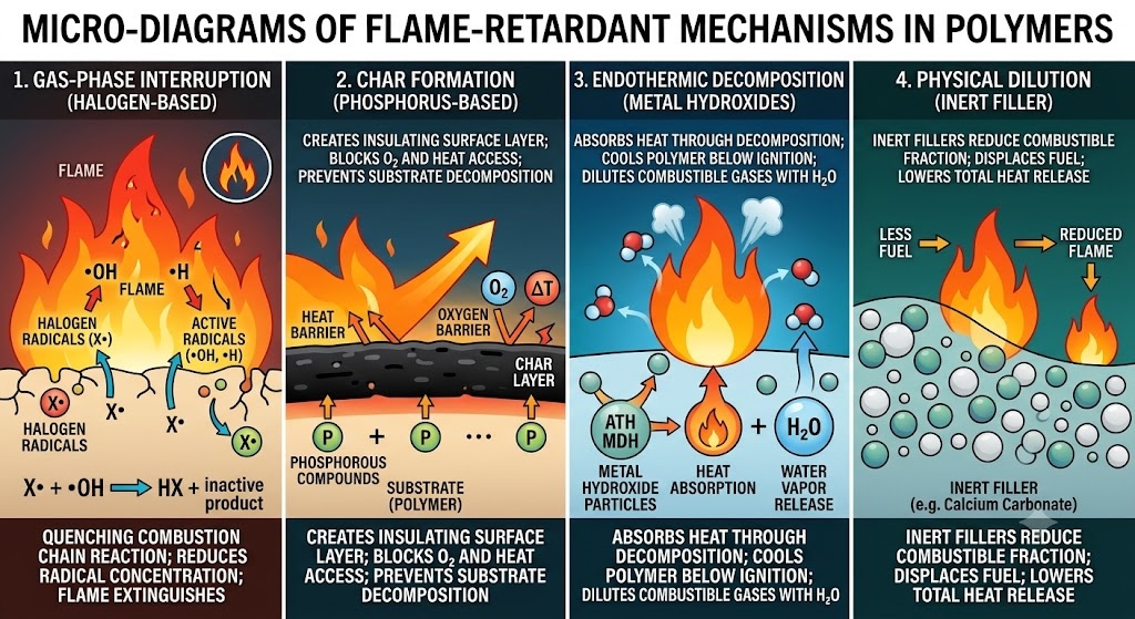
Flame retardants address this by one or more mechanisms:
- Gas phase interruption — FR radicals quench the combustion chain reaction in the flame zone (halogen-based systems)
- Char formation — FR chemistry promotes a carbonaceous surface layer that insulates the substrate from the flame (phosphorus-based, intumescent systems)
- Endothermic decomposition — FR additive absorbs heat through decomposition, cooling the substrate below ignition temperature (metal hydroxides: ATH, MDH)
- Physical dilution — inert filler reduces the combustible fraction of the compound
The challenge for the injection moulder is that these mechanisms are activated by heat — the same stimulus driving the moulding process. FR additives that are thermally stable enough to survive the barrel, but reactive enough to perform in a fire, represent a narrow engineering window with direct consequences for processing and tooling.
2. The UL94 Rating System: What the Classifications Actually Mean
UL94 (Standard for Tests for Flammability of Plastic Materials for Parts in Devices and Appliances) is the primary global reference for plastic flammability classification. Understanding what each rating demands — and does not demand — is essential for correct specification.
2.1 Test Method Overview
UL94 tests are conducted on moulded specimens, not raw material. Specimen geometry matters: the standard specifies thickness categories (typically 0.8 mm, 1.6 mm, 3.2 mm), and ratings are thickness-dependent. A material rated V-0 at 3.2 mm may only achieve V-2 at 0.8 mm.
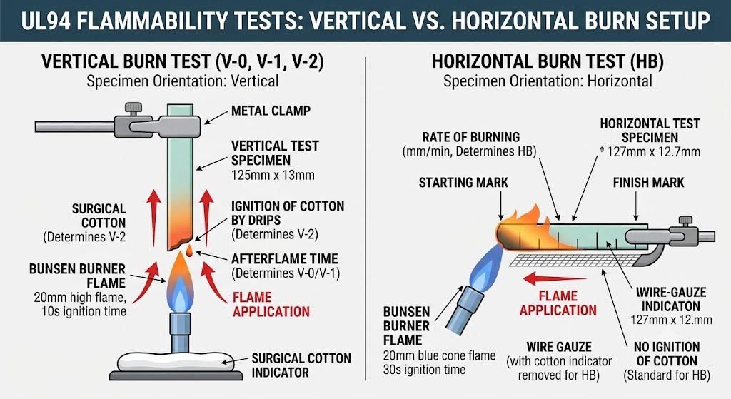
The two primary test series:
Vertical burn tests (V-0, V-1, V-2, 5VA, 5VB): A 125 mm × 13 mm specimen is held vertically and exposed to a defined flame for two 10-second intervals. Dripping, afterflame time, and ignition of a cotton indicator below the specimen determine the rating.
Horizontal burn test (HB): A 127 mm × 12.7 mm specimen is held horizontally. This is the lowest classification — most commodity polymers with no FR treatment achieve HB at sufficient thickness.
2.2 Classification Criteria
| Rating | Afterflame ≤ (each application) | Total afterflame ≤ (5 specimens) | Dripping ignites cotton? | Afterglow ≤ | Notes |
|---|---|---|---|---|---|
| V-0 | 10 sec | 50 sec | No | 30 sec | Most stringent vertical |
| V-1 | 30 sec | 250 sec | No | 60 sec | Mid-tier vertical |
| V-2 | 30 sec | 250 sec | Yes allowed | 60 sec | Dripping permitted |
| 5VA | — | — | No | — | No burn-through on plaque; more stringent than V-0 |
| 5VB | — | — | No | — | Burn-through on plaque permitted; more stringent than V-1 |
| HB | Burns ≤ 76 mm/min (>3mm) or extinguishes | — | N/A | — | Lowest; most commodity plastics |
2.3 Ratings in Practice: What Regulators and OEMs Actually Specify
| Application | Minimum UL94 Requirement | Notes |
|---|---|---|
| Consumer electronics enclosures (IEC 62368-1) | V-1 or V-0 | Depends on wall thickness and internal heat source |
| EV battery housing and BMS enclosures | V-0 at ≤1.6 mm | Often reinforced by OEM-specific thermal runaway requirements |
| Automotive electrical connectors (USCAR-2) | V-0 at ≤0.8 mm | Very thin wall — narrows material options significantly |
| Household appliance housings (IEC 60335) | V-1 or V-0 | Category-dependent |
| Industrial electrical enclosures (IEC 61439) | V-0 or 5VA | 5VA increasingly specified for large enclosures |
| Aircraft interior components (FAR 25.853) | Not UL94 — uses OSU heat release and vertical bunsen tests | UL94 is insufficient for aerospace |
| Building and construction (EN 13501) | Euroclass B–E system, not UL94 | Different test standard entirely |
Critical point: UL94 ratings are reported by suppliers for specific colours, thicknesses, and lot certifications. A black PC/ABS housing achieving V-0 does not guarantee V-0 in white or natural — FR additive interaction with pigment systems affects performance, and the UL94 yellow card lists approved colours explicitly.
3. Major FR Chemistry Families and Their Processing Profiles
3.1 Halogenated Flame Retardants (Brominated / Chlorinated)
Mechanism: Halogen radicals interrupt the combustion chain reaction in the gas phase. Highly effective at low loading levels (5–15 phr), enabling V-0 with minimal impact on mechanical properties.
Common systems:
- Decabromodiphenyl ethane (DBDPE) + antimony trioxide synergist — ABS, HIPS, PA
- Tetrabromobisphenol A (TBBPA) oligomers — PC/ABS blends
- Chlorinated paraffins — lower-cost commodity applications
Processing behaviour:
- Thermally stable to 280–300°C in most formulations — compatible with ABS, PA66, PC processing temperatures
- Above 300°C, HBr/HCl gas generation accelerates sharply — barrel temperature exceedances cause corrosive gas release
- Purging with a neutral carrier (HDPE or PP) is mandatory when shutting down — trapped brominated material degrades and attacks barrel and screw surfaces
- Corrosive to standard tool steel: HBr and HCl generated at any process deviation attack P20 and H13. Not severe under normal conditions but cumulative over high-volume production
Tooling implications:
- Standard P20 cavity steel acceptable for well-controlled processes
- Plating (hard chrome or electroless nickel) recommended for high-volume or any process running near upper temperature limit
- Purge protocol must be documented in process instructions — flash-induced burning episodes cause localised corrosion pits at gates and vents
Regulatory status: REACH SVHC list includes several brominated FR compounds. RoHS Directive restricts PBB and PBDE. DBDPE is currently unrestricted in the EU and US but subject to ongoing review. Specify only REACH/RoHS-compliant grades — verify supplier declaration annually.
3.2 Phosphorus-Based Flame Retardants (Halogen-Free)
Mechanism: Promotes char layer formation on the polymer surface, physically blocking oxygen access and insulating the substrate. Some phosphorus systems also have gas-phase activity.
Common systems:
- Resorcinol bis(diphenyl phosphate) (RDP) — PC/ABS blends (primary system for halogen-free V-0 PC/ABS)
- Aluminium diethylphosphinate (AlPi, Clariant Exolit® OP series) — PA6, PA66, PBT
- Melamine polyphosphate (MPP) — PA6, PA66
- Red phosphorus — PA, PBT (rarely used now due to handling hazards)
Processing behaviour:
- RDP in PC/ABS: reduces melt viscosity (acts as plasticiser at processing temperature) → increases flash risk, reduces clamp force margin
- AlPi in PA grades: thermally stable to 320°C, minimal viscosity effect — most process-friendly FR system currently available
- MPP in PA: moderate stability; above 290°C, ammonia and melamine vapour generation causes surface blistering and silver streaking — keep melt temperature at lower end of PA range
- All phosphorus systems: moisture uptake in storage degrades performance and causes splay/silver streaks — drying specifications are tighter than unfilled grades
Drying requirements (phosphorus FR grades):
| Base Polymer | Standard Grade Drying | FR Grade Drying | Additional Notes |
|---|---|---|---|
| PA6 | 80°C / 4 hr | 85°C / 6–8 hr | MPP grades especially moisture-sensitive |
| PA66 | 85°C / 4 hr | 90°C / 6–8 hr | AlPi grades more forgiving |
| PBT | 120°C / 4 hr | 130°C / 5–6 hr | FR PBT very moisture-sensitive |
| PC/ABS | 90°C / 3–4 hr | 95°C / 4–6 hr | RDP migrates on storage — use promptly after opening |
Tooling implications:
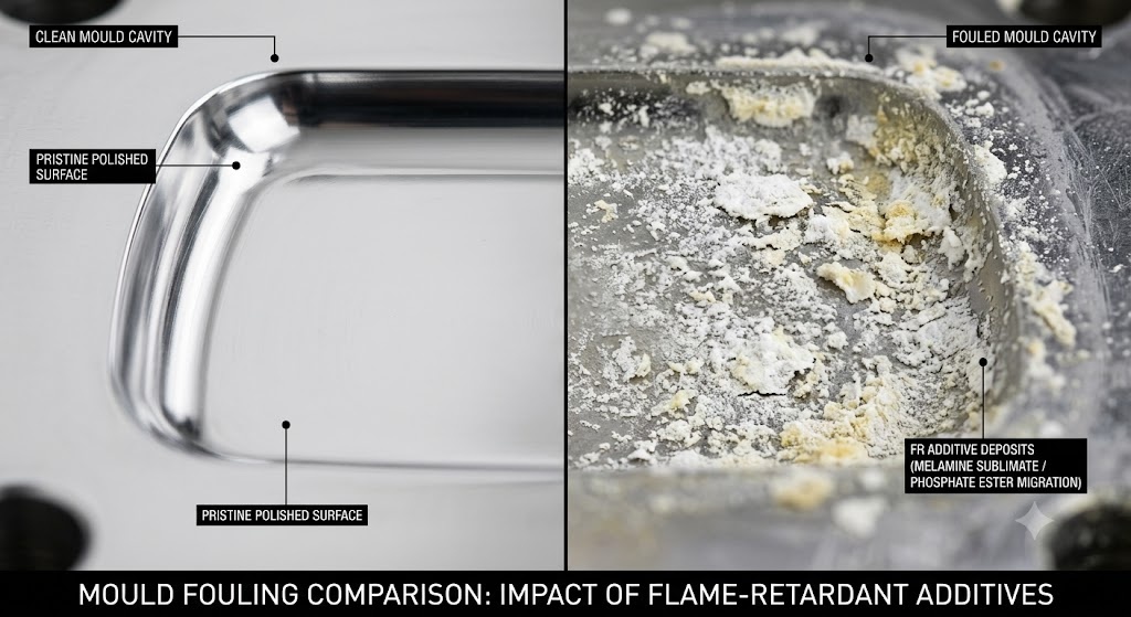
- RDP migration: In PC/ABS with RDP, the phosphate ester can migrate to the part surface and to the mould cavity over time. This causes:
- Mould deposit buildup on cavity surfaces (white or yellow residue) requiring cleaning every 50,000–150,000 shots depending on run conditions
- Surface gloss reduction on the part if mould is not cleaned — critical for Class A surfaces
- Stainless steel (S136) or hard-chrome plated P20 reduces deposit adhesion and simplifies cleaning
- AlPi grades in PA are the most tooling-friendly FR system — minimal deposit, minimal corrosion
3.3 Nitrogen-Based Flame Retardants (Melamine Systems)
Mechanism: Primarily gas phase dilution through nitrogen release; some char promotion when combined with phosphorus (intumescent systems).
Common systems:
- Melamine cyanurate (MC) — PA6, PA66 (V-2 achievable, V-0 difficult without synergist)
- Melamine polyphosphate (MPP) — PA6, PA66 (V-0 achievable in combination)
- Intumescent systems (APP + pentaerythritol + melamine) — PP, PE (primarily for halogen-free cable and film applications)
Processing behaviour:
- MC in PA: decomposes at 320°C releasing isocyanic acid and melamine vapour — hard upper limit on melt temperature of 290°C for PA66/MC compounds
- Sublimation of melamine at the mould cavity surface forms white powdery deposits — requires frequent cavity cleaning
- Intumescent PP systems: very shear-sensitive; high injection speeds cause FR component separation and streaking
Tooling implications:
- Melamine sublimate deposits are the most aggressive mould fouling problem in the FR grade category
- Chrome-plated or PVD-coated cavities dramatically reduce deposit adhesion — maintenance interval 2–3× longer than uncoated
- Vent blockage from deposits is a significant risk — vents must be designed for accessibility and cleaned on a defined schedule (typically every 30,000–80,000 shots)
3.4 Metal Hydroxide Flame Retardants (ATH, MDH)
Mechanism: Endothermic decomposition releases water vapour, cooling the substrate and diluting combustible gases. No halogen, no phosphorus, no nitrogen — the cleanest chemistry from a processing by-product standpoint.
Common systems:
- Aluminium trihydrate (ATH) — decomposes at 180–200°C; limits use to polymers processed below 200°C (EVA, LDPE, PVC)
- Magnesium dihydroxide (MDH, brucite) — decomposes at 300–320°C; extends applicability to PP, PA6
Processing behaviour:
- Very high loading required (40–65% by weight) to achieve V-0 — dramatically increases compound density and reduces mechanical properties
- High filler loading increases melt viscosity significantly — higher injection pressures required, longer fill times
- Abrasive to screws, barrels, and mould cavities — wear rate is high, similar to glass-filled grades
- MDH/ATH compounds have very low LOI improvement efficiency per unit loading compared to halogen/phosphorus systems — rarely used where V-0 at thin wall is required
Tooling implications:
- Treat as equivalent to GF30–GF40 for wear purposes
- Hardened gate inserts (≥52 HRC) mandatory
- Runner and gate design must minimise shear (larger diameters than unfilled equivalent) to prevent filler agglomeration and gate erosion
- Cavity steel: H13 or equivalent hardened tool steel — P20 is marginal for high-volume ATH/MDH production
4. Processing Parameter Adjustments for FR Grades
Table: Process Window Adjustments vs. Base Polymer
| Parameter | Direction | Magnitude | Rationale |
|---|---|---|---|
| Melt temperature | Lower | 5–20°C below standard | Prevent FR thermal decomposition |
| Barrel residence time | Minimise | Design for <5 min max | Degradation is time × temperature dependent |
| Injection speed | Reduce | 10–20% | Reduce shear-induced decomposition; reduce flash risk (RDP) |
| Back pressure | Reduce | 10–20% below standard | Reduce shear heat generation |
| Screw speed | Reduce | 10–15% RPM | Same rationale |
| Purge protocol | Mandatory | Per shutdown every time | Prevent corrosive degradation between runs |
| Drying | Increase temp and time | See Table in Section 3.2 | FR grades more moisture-sensitive |
| Mould temperature | Lower end of range | Where possible | Reduce deposit formation (melamine systems) |
| Hot runner temperature | Minimum viable | As low as fill allows | Most critical zone for FR degradation |
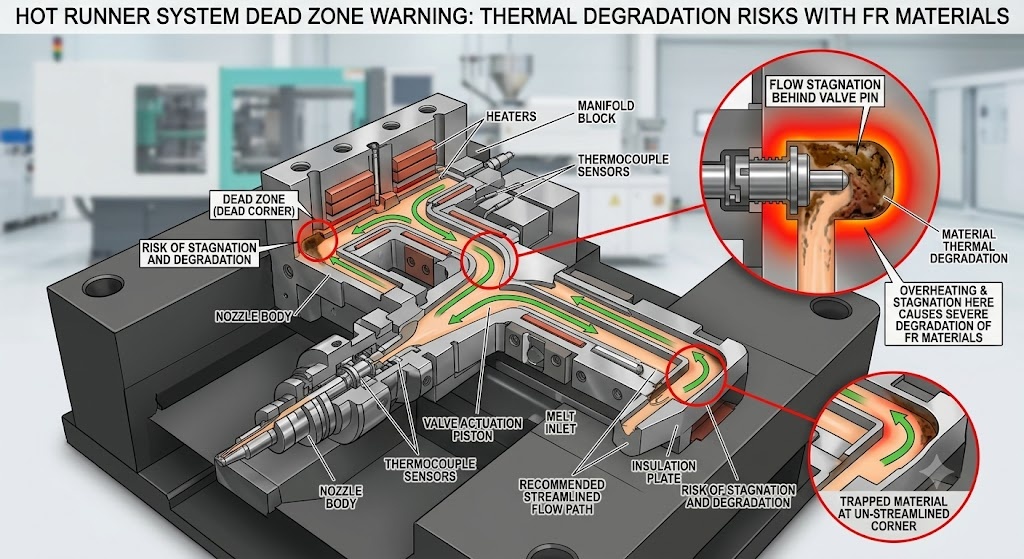
Hot Runner Considerations
Hot runners are the highest-risk zone for FR material degradation. The manifold and nozzle tips maintain the melt at temperature continuously — and in dead zones (behind valve stems, in poorly designed manifold bends), residence time can be 30–60 minutes. This is sufficient to degrade most FR systems.
Mandatory hot runner design requirements for FR grades:
- Full streamline (no dead corners) manifold geometry — specify to hot runner supplier
- Minimum manifold volume consistent with fill requirements — oversized manifolds increase residence time
- Independent zone temperature control per nozzle — allows precise minimum temperature management
- Valve gate preferred over open gate — allows positive shutoff during production stoppages
- Temperature drop at shutdown: reduce to 150–170°C immediately on any production pause >5 minutes
5. Mould Steel and Surface Treatment Selection
Table: Recommended Mould Steel by FR Chemistry
| FR System | Base Polymer | Cavity Steel | Core Steel | Gate Insert | Surface Treatment | Notes |
|---|---|---|---|---|---|---|
| Brominated (DBDPE) | ABS, HIPS | P20 or S136 | P20 | H13 hardened | Hard chrome or EN plating | Plating critical for high volume |
| RDP (phosphate ester) | PC/ABS | S136 preferred | P20 | S136 | PVD or EN plating | Deposit adhesion lowest on S136 |
| AlPi (aluminium phosphinate) | PA, PBT | P20 or H13 | P20 | H13 | Optional chrome | Most tooling-friendly FR system |
| Melamine (MC, MPP) | PA6, PA66 | P20 + chrome or S136 | P20 | H13 | Hard chrome mandatory | Sublimate deposits severe without coating |
| ATH / MDH (metal hydroxide) | PP, PA, EVA | H13 hardened | H13 | H13 or carbide | Chrome or PVD | Treat as abrasive filler compound |
| Inherent (PPS, PEEK) | PPS, PEEK | S136 or 420SS | S136 | S136 | Optional | Corrosive at melt temp; base steel corrosion risk |
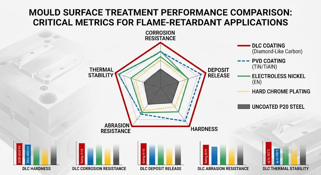
Surface Treatment Performance Comparison for FR Applications
| Treatment | Corrosion Resistance | Deposit Release | Hardness (HV) | Max Temp | Cost Premium |
|---|---|---|---|---|---|
| Hard chrome plating | Good | Moderate | 900–1100 | 400°C | +15–25% |
| Electroless nickel (EN) | Excellent | Good | 500–700 | 260°C | +10–20% |
| PVD (TiN, TiAlN) | Good | Good–Excellent | 2000–3300 | 400–600°C | +20–35% |
| DLC (Diamond-Like Carbon) | Excellent | Excellent | 3000–5000 | 300°C | +30–50% |
| Uncoated P20 | Poor | Poor | 300–350 | — | Baseline |
DLC coating delivers the best deposit release performance for melamine-system FR grades — particularly valuable for high-volume PC/ABS and PA enclosure production where cavity cleaning downtime is significant.
6. Vent Design for FR Grades
Flame-retardant compounds generate more outgas than unfilled grades — decomposition by-products, moisture from metal hydroxides, and volatile additives all create gas that must be evacuated from the cavity. Insufficient venting causes:
- Diesel effect burning at last-fill locations — char deposits that are often misdiagnosed as gate blush or material degradation
- Short shots from gas back-pressure in thick sections
- Surface blistering from trapped moisture or volatile FR components
Vent Depth Recommendations for FR Grades
| Material / FR System | Vent Depth (land, mm) | Vent Width (mm) | Vent Relief Depth (mm) | Cleaning Interval |
|---|---|---|---|---|
| ABS / brominated FR | 0.012–0.018 | 5–8 | 0.5 | Every 100,000 shots |
| PC/ABS / RDP | 0.010–0.015 | 5–8 | 0.5 | Every 80,000 shots |
| PA66 / AlPi | 0.010–0.015 | 4–6 | 0.3 | Every 120,000 shots |
| PA6 / melamine | 0.008–0.012 | 4–6 | 0.3 | Every 30,000–50,000 shots |
| PP / ATH intumescent | 0.015–0.020 | 6–10 | 0.5 | Every 80,000 shots |
| PPS (inherent FR) | 0.005–0.008 | 3–5 | 0.2 | Every 150,000 shots |
Melamine-based FR compounds have the most aggressive vent fouling behaviour. A production mould running PA6/MC that is not cleaned on schedule will have blocked vents within 50,000 shots — leading to burning, short shots, and part rejection.
Design recommendation: For FR grades with high outgassing tendency (melamine, intumescent systems), design vents as replaceable inserts where possible. This allows vent cleaning offline while the mould continues running with a clean spare set.
7. Quality and Compliance Considerations
7.1 UL94 Yellow Card Verification
The UL94 rating printed on a material datasheet is a supplier’s marketing claim. The authoritative source is the UL Product iQ database (formerly Yellow Card). Before specifying an FR material for a UL94-regulated application, verify:
- The exact grade and lot matches a current Yellow Card listing
- The rating applies to the wall thickness of your part — many materials lose one rating class at thinner walls
- The colour is listed — pigment systems affect FR performance
- The certificate expiry date is current — UL conducts periodic re-testing and ratings can be withdrawn
7.2 Colour Impact on FR Performance
Pigment systems interact with FR additives in ways that can reduce performance by one full UL94 class. Carbon black (used in black compounds) generally improves FR performance — it promotes char formation. White pigments (TiO₂) are neutral to mildly negative. Organic pigments (particularly yellow and red azo pigments) can interfere with phosphorus FR systems.
Rule: Always qualify FR performance on the production colour, not natural or black reference data only. If a customer requires V-0 in multiple colours, obtain UL Yellow Card verification for each colour separately.
7.3 Weld Line and Knit Line FR Performance
The weld line region of an injection-moulded FR part typically shows reduced flame retardancy compared to the bulk. In the weld zone, glass fibres align parallel to the flow front, and FR additive distribution can be non-uniform. Testing should include specimens cut from weld line regions for applications with critical fire safety requirements.
7.4 Regrind and Recycling
FR additives — particularly halogenated systems — complicate end-of-life recyclability. Within-process regrind (sprues, runners, rejected parts) from brominated FR compounds requires:
- Maximum regrind ratio: 10–15% by weight — higher ratios degrade FR performance and increase gas generation
- Regrind must not be mixed across FR chemistry families — brominated regrind contaminating halogen-free compounds creates compliance uncertainty
- Document regrind ratio in process records for traceability
8. Troubleshooting: Common FR-Grade Defects and Root Causes
| Defect | Likely FR-Related Cause | Corrective Action |
|---|---|---|
| Silver streaks / splay | Moisture in FR compound; volatile FR decomposition | Increase drying time/temp; reduce melt temperature; check material storage |
| Yellow/brown discolouration at gate | FR thermal decomposition at hot runner nozzle | Reduce nozzle temperature; minimise residence time; purge more frequently |
| White deposits on cavity surface | Melamine sublimation (MC/MPP systems) or RDP migration | Clean cavity with appropriate solvent; increase cleaning frequency; consider DLC coating |
| Burning at last-fill location | Insufficient venting; outgas from FR decomposition | Add or deepen vents at burn location; reduce injection speed |
| Flash (new onset) | RDP acting as plasticiser reducing viscosity | Reduce melt temperature; check material MFI vs. previous lot; reduce injection speed |
| Reduced gloss | Mould deposits from FR migration | Clean cavity; apply PVD or DLC coating |
| Short shots (previously stable tool) | Blocked vents from FR deposits | Clean vents immediately; implement scheduled vent maintenance |
| Delamination / layer separation | Incompatible regrind contamination; moisture | Eliminate regrind contamination; verify drying; check lot certification |
| UL94 test failure on production parts | Colour change without re-qualification; regrind over-ratio; wall thinner than certified | Re-qualify colour; reduce regrind; verify wall thickness at thin sections |
9. Conclusion
Flame-retardant injection moulding grades present a unique combination of process sensitivity, tooling aggression, and compliance complexity that standard engineering thermoplastics do not. The consequences of mismanaging FR materials extend beyond part quality — degraded FR compounds can corrode screws and barrels, block vents, deposit on cavities, and in the worst case generate toxic gas in the processing environment.
The path to reliable FR grade production is systematic: select the right FR chemistry for the application temperature and regulatory requirement, specify mould steel and surface treatments appropriate to that chemistry, implement tighter drying and process controls, and establish preventive maintenance schedules that account for the accelerated fouling and wear characteristics of FR compounds. Engineering these factors in at the design stage costs a fraction of what correcting them in production does.
Related Articles:
- EV Battery Housing Injection Molding: PA66 GF50 vs. PPS GF40 — Engineering Tradeoffs
- Top 8 Injection Molding Materials for 2026
- Selection Guide for High-Precision Injection Mold Steel
- Mould Flashing in Injection Molding: Causes, Prevention, and Elimination
- Achieving Optimal Surface Finish in Plastic Injection Molding
IMTEC Mould | Nr.818 Jinyuan Road, Yinzhou, Ningbo, 315100, Zhejiang, China | [email protected] | +86 153 5648 7586

