 English
 Indonesia
Flash is one of the most common defects in injection molding — and one of the most misdiagnosed. Thin fins of excess material appearing at parting lines, ejector pins, or insert interfaces are frequently blamed on process parameters alone, when the root cause is often tooling. This guide provides a systematic diagnostic framework covering all seven root cause categories, quantified prevention standards, and a corrective action priority matrix to eliminate flash efficiently.
1. What Is Mould Flashing?
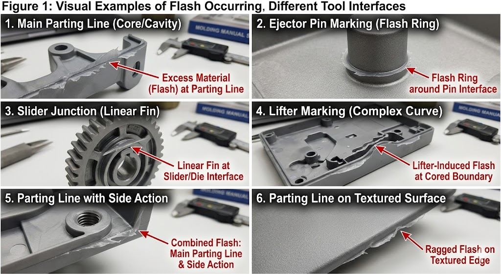
Flash (also: flashing, burr) is excess material that escapes the mould cavity through any gap in the tool before freezing. It appears as a thin fin, web, or feathered edge attached to the part at:
- Parting lines — the most common location
- Ejector pin interfaces — circular flash rings around pin faces
- Slide and lifter interfaces — linear fins along side action contact faces
- Insert boundaries — at metal insert perimeters in insert moulding
- Vent locations — if vents are oversized or eroded
- Shut-off surfaces — in cored features and through-holes
Flash is not merely cosmetic. It adds secondary trimming operations, risks assembly interference, creates sharp edges (injury and seal failure hazard), and in medical or food-contact applications triggers regulatory non-conformance. More importantly, it signals a gap in the mould system that, if untreated, widens progressively with each shot.
2. The Seven Root Cause Categories
Flash always has the same immediate cause — material under pressure finding a gap. But the origin of that gap falls into seven distinct categories, each requiring a different corrective action.
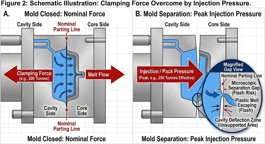
2.1 Insufficient Clamping Force
The most frequently overlooked cause. If injection pressure exceeds the press’s effective clamping force on the projected area of the part and runner system, the mould plates separate momentarily during fill and pack — creating a dynamic gap at the parting line.
Diagnostic check:
Required clamp force (tonnes) = Projected area (cm²) × Cavity pressure (MPa) ÷ 100
For a part with 180 cm² projected area (including runners) filled at 80 MPa average cavity pressure:
Required clamp = 180 × 80 ÷ 100 = 144 tonnes minimum
Add a 20–25% safety margin → 175–180 tonnes minimum.
Running this part on a 150-tonne press will produce parting line flash regardless of any other parameter adjustment.
Common mistake: Calculating projected area from the part only, excluding the runner system. Sprue, runners, and gates contribute significant projected area and cavity pressure.
| Material | Typical Cavity Pressure Range | Clamping Force Rule of Thumb |
|---|---|---|
| PP, PE (thin wall) | 40–80 MPa | 0.4–0.8 t/cm² |
| ABS, PS | 50–90 MPa | 0.5–0.9 t/cm² |
| PA6, PA66 | 60–100 MPa | 0.6–1.0 t/cm² |
| PC, PC/ABS | 80–130 MPa | 0.8–1.3 t/cm² |
| PPS, LCP | 90–150 MPa | 0.9–1.5 t/cm² |
| POM | 70–110 MPa | 0.7–1.1 t/cm² |
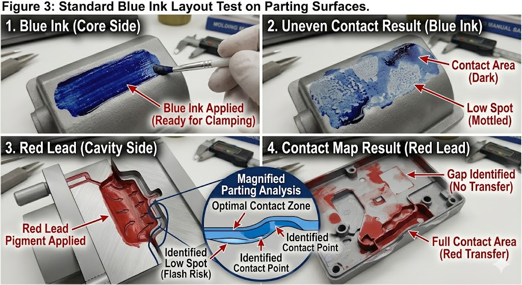
2.2 Parting Surface Wear or Damage
The parting surface (PS) is the primary seal between cavity and atmosphere. Any deviation from perfect flatness — whether from wear, impact damage, EDM spark erosion, or inadequate surface hardness — allows material to escape.
Critical tolerances:
| Mould Size | Max Allowable PS Flatness Deviation | Recommended Steel Hardness |
|---|---|---|
| Small (<250 × 250 mm) | 0.005 mm | 48–52 HRC |
| Medium (250–500 mm) | 0.008 mm | 48–52 HRC |
| Large (>500 mm) | 0.010–0.012 mm | 44–48 HRC |
Inspection protocol: Blue ink transfer test or feeler gauge sweep across the full parting surface. Any gap >0.010 mm on a commodity material or >0.005 mm on a low-viscosity material (LCP, PPS) is a flash risk.
Repair methods by severity:
| Damage Type | Repair Method | Lead Time |
|---|---|---|
| Minor wear (<0.05 mm low area) | Laser welding + re-polish | 1–3 days |
| Moderate wear (0.05–0.2 mm) | Spray welding or TIG weld + re-machine | 3–5 days |
| Impact damage / dent | Laser welding + EDM re-spark | 2–4 days |
| Widespread wear (>0.2 mm) | Full PS re-skim on surface grinder | 3–7 days |
| Repeated flash same location | Hardface weld (Stellite) + re-polish | 5–10 days |
2.3 Excessive Injection Speed or Pressure
Even a geometrically perfect mould will flash if process parameters push cavity pressure beyond the clamp force capacity, or if the injection velocity is high enough to create a hydraulic wedge effect at the parting line before the clamp tonnage fully develops.
Flash-inducing process conditions:
- Injection speed set so high that cavity fills in <0.3 sec — peak pressure spike exceeds clamp capacity momentarily
- Pack pressure set above 80% of injection pressure on a low-viscosity material
- Hold time extended beyond gate freeze — continued pressure after gate freeze transfers force to mould plates, not part packing
- Melt temperature too high — reduces viscosity, material flows more aggressively into any gap
Process adjustment sequence (before tooling intervention):
- Reduce injection speed in 10% increments — check if flash reduces
- Reduce pack pressure to 60–70% of fill pressure
- Verify hold time does not exceed gate freeze-off time (use gate freeze study)
- Reduce melt temperature by 5–10°C
- If flash persists after all four adjustments — the root cause is tooling, not process
2.4 Material Viscosity Too Low
Low-viscosity materials flow into gaps that standard-viscosity materials bridge. This is why PPS, LCP, and low-molecular-weight PA grades require tighter parting surface tolerances than ABS or PP.
Melt Flow Index (MFI) as a flash risk indicator:
| MFI Range (g/10 min) | Flash Risk Category | Max Allowable PS Gap |
|---|---|---|
| < 5 | Low | 0.020 mm |
| 5–20 | Moderate | 0.015 mm |
| 20–50 | High | 0.010 mm |
| > 50 (e.g., LCP, thin-wall PP) | Very High | 0.005–0.008 mm |
Material lot variation: MFI can vary ±15–25% between lots within the same grade. A mould running at the flash threshold with one lot may flash with the next. Always check incoming MFI against mould qualification data.
2.5 Mould Temperature Too High
Elevated mould temperature reduces the viscosity of the melt layer in contact with the parting surface, extending the time window during which material is fluid enough to penetrate gaps. This is particularly significant for:
- Crystalline materials with sharp melting points (POM, PPS, PA)
- Materials run near the upper limit of their recommended mould temperature range
- Hot runner moulds where manifold heat soak can elevate mould plate temperature locally
Rule of thumb: Every 10°C increase in mould temperature above the recommended minimum increases flash sensitivity by approximately one viscosity grade — equivalent to a 20% increase in MFI.
2.6 Mould Design Deficiencies
Geometric features in the mould design that create inherent flash risk:
Unsupported parting surface spans: Large flat parting surfaces without support pillars deflect under cavity pressure. A 400 × 400 mm unsupported mould plate in P20 steel deflects 0.03–0.08 mm at 80 MPa — sufficient to produce flash on the perimeter.
Support pillar design rule: Maximum unsupported span between support pillars = 150 mm for medium-duty moulds. Add pillars at 120–130 mm centres for high-pressure materials (PC, PPS).
Insufficient land width at parting line: The “land” — the narrow flat band immediately adjacent to the cavity on the parting surface — must be wide enough to resist pressure-induced deformation. Recommended minimum land width:
| Material | Minimum Land Width |
|---|---|
| PP, PE, ABS | 3–5 mm |
| PA, POM, PC | 5–8 mm |
| PPS, LCP | 8–12 mm |
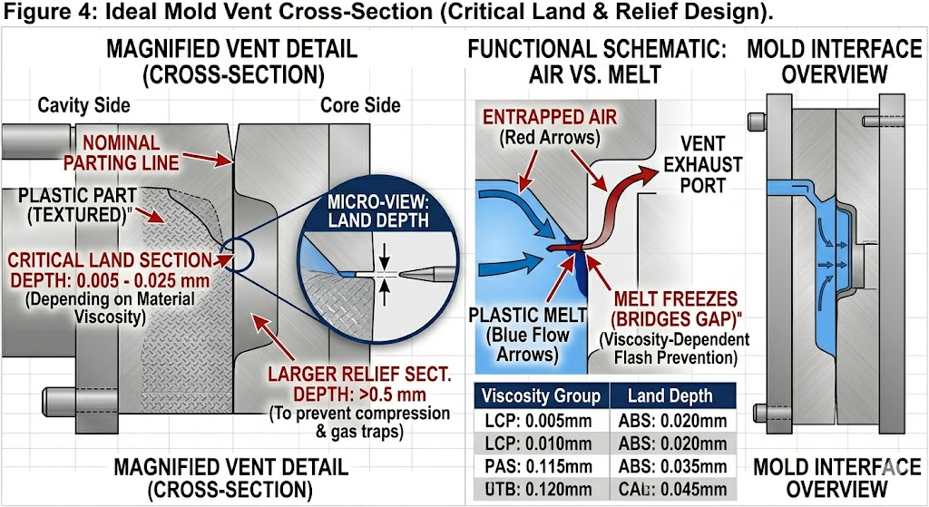
Vent depth too deep: Vents are intentional gaps — if oversized, they become flash generators. Standard vent depth guidelines:
| Material | Vent Depth (land section) | Vent Depth (relief section) |
|---|---|---|
| PP, PE | 0.015–0.025 mm | 0.5–0.8 mm |
| ABS, PS | 0.010–0.020 mm | 0.5–0.8 mm |
| PA, POM | 0.010–0.015 mm | 0.3–0.5 mm |
| PC, PC/ABS | 0.008–0.015 mm | 0.3–0.5 mm |
| PPS, LCP | 0.005–0.010 mm | 0.2–0.3 mm |
2.7 Worn or Misaligned Moving Components
Side actions, lifters, core pulls, and ejector pins create dynamic interfaces that move every cycle. These interfaces wear progressively and are the most common source of flash in high-volume production that was previously flash-free.
Ejector pin flash: Clearance between pin diameter and hole diameter must be held within tight limits. Standard clearance by material:
| Material | Ejector Pin Clearance (per side) |
|---|---|
| PP, PE, ABS | 0.010–0.020 mm |
| PA, POM | 0.008–0.015 mm |
| PC, PC/ABS | 0.005–0.012 mm |
| PPS, LCP | 0.003–0.008 mm |
Clearances above these limits produce visible pin flash. Below them, pins bind and break. This is a wear management problem — pin clearances should be verified every 100,000–200,000 shots on high-volume tools.
Slide and lifter interface flash: Wear on the wear plates (gibs) that guide side actions allows the slide face to shift 0.01–0.05 mm from its seating face — sufficient for flash. Gib wear plates should be replaceable components on any production mould, with inspection intervals defined in the mould maintenance plan.
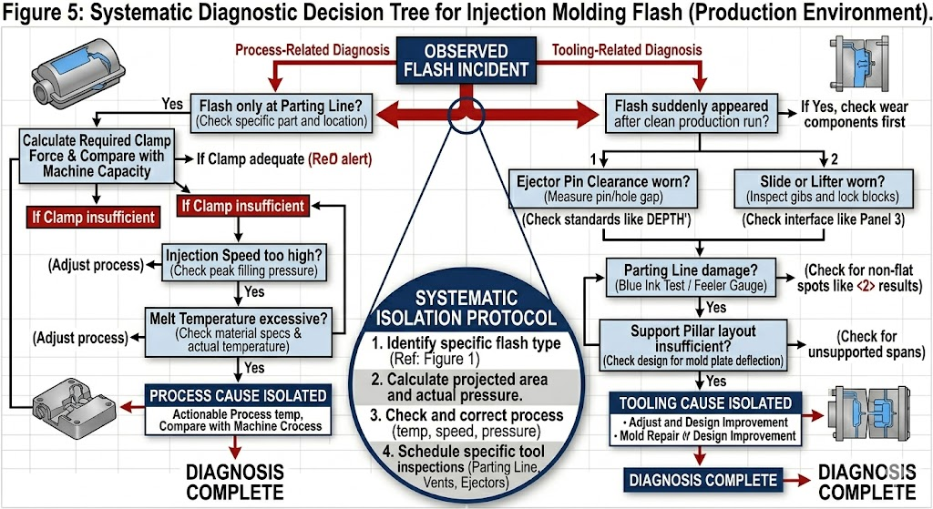
3. Flash Diagnostic Decision Tree
Use this sequence to identify root cause without unnecessary mould disassembly:
FLASH OBSERVED
│
├── Flash only at parting line?
│   ├── YES → Check clamp force calculation first
│   │         → Then inspect PS flatness (blue ink test)
│   │         → Then reduce injection speed / pack pressure
│   └── NO  → Continue below
│
├── Flash at ejector pins only?
│   └── YES → Measure pin-to-hole clearance
│             → Check pin length (long pins = higher contact pressure)
│             → Verify ejector plate return is fully seated before clamp closes
│
├── Flash at slide/lifter interface?
│   └── YES → Inspect gib wear plates (feeler gauge)
│             → Check slide seating force / locking angle
│             → Verify heel block contact
│
├── Flash at vents?
│   └── YES → Measure vent depth (target: re-cut to spec)
│             → Check for vent erosion (abrasive glass-filled material)
│
├── Flash suddenly appeared after X shots of clean production?
│   └── YES → Wear-related cause (gib, parting surface, ejector pins)
│             → Schedule mould inspection / preventive maintenance
│
└── Flash present from first shot of new mould?
    └── YES → Design or build quality issue
              → Verify clamp force calculation
              → Verify parting surface grind quality
              → Check support pillar layout
              → Verify vent depths against spec
4. Prevention Standards by Mould Build Phase
The most cost-effective flash prevention happens before the mould runs its first shot.
4.1 Design Phase
- Run Moldflow cavity pressure simulation — verify peak cavity pressure × projected area does not exceed 80% of planned press clamp capacity
- Design support pillars at ≤150 mm centres for all cavity pressure >60 MPa
- Specify minimum land width per material category (Section 2.6)
- Design vent depth to material specification — do not rely on default machining allowances
- Specify ejector pin clearance in mould drawing — it must appear on the tolerance block, not be left to machinist judgment
4.2 Mould Build Phase
- Verify parting surface flatness on surface grinder before final assembly — document measurement
- Blue ink test after full assembly — 100% parting surface contact required before first trial
- Measure and record all ejector pin clearances — minimum 5 sample pins per mould, full set for critical moulds
- Verify slide seating under press clamping load before first injection — use clay or Fuji Prescale film
4.3 First Article Trial Phase
- Start at 50% injection speed and 60% pack pressure — increase incrementally
- Record process window upper boundary (flash onset) — this is a critical mould qualification parameter
- Document process window width: difference between short-shot onset and flash onset should be ≥15% of injection pressure for a robust mould
4.4 Production Phase
- Define preventive maintenance intervals for: parting surface inspection (every 200,000 shots), gib wear plate measurement (every 150,000 shots), ejector pin clearance check (every 100,000 shots for high-volume tools)
- Track flash incidents by location in the SPC system — progressive flash at one location signals wear before it becomes a quality escape
- Maintain material MFI incoming inspection records — correlate flash incidents with MFI data
5. Corrective Action Priority Matrix
When flash is observed in production, use this matrix to prioritize corrective actions by cost and effectiveness:
| Action | Cost | Time to Implement | Effectiveness | Priority |
|---|---|---|---|---|
| Reduce injection speed / pack pressure | Zero | Immediate | High (if process-caused) | 1st |
| Verify clamp force adequacy — move to larger press | Low | Same shift | Definitive for clamp-caused flash | 2nd |
| Blue ink test — identify PS contact gap | Low | 2–4 hours | Diagnostic, not corrective | 3rd |
| Laser weld repair of PS low spots | Medium | 1–3 days | Permanent for wear-caused flash | 4th |
| Replace worn gib wear plates | Low–Medium | 4–8 hours | Permanent for slide flash | 5th |
| Replace ejector pins (oversized clearance) | Low | 4–8 hours | Permanent for pin flash | 6th |
| Re-grind parting surface | Medium | 3–7 days | Permanent for widespread PS wear | 7th |
| Add support pillars (design deficiency) | High | 2–4 weeks | Permanent for deflection-caused flash | 8th |
| Increase steel hardness (re-insert in harder steel) | High | 3–6 weeks | Long-term wear prevention | 9th |
6. Special Cases: High-Flash-Risk Materials
PPS and LCP
Both materials have melt viscosities 3–5× lower than ABS at processing temperatures. They will find and exploit any gap that standard materials bridge. Moulds running PPS or LCP must be built to tighter tolerances from the start — retrofitting a standard-tolerance mould to run PPS is rarely cost-effective.
Mandatory requirements:
- S136 or 420SS cavity steel (corrosion and hardness)
- Parting surface flatness ≤0.005 mm
- Ejector pin clearance ≤0.006 mm per side
- Vent depth ≤0.008 mm land section
- Support pillars at 120 mm maximum centres
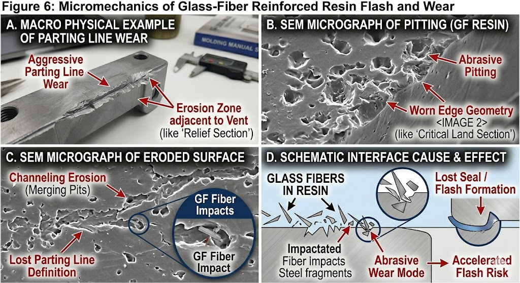
Glass-Filled Grades (GF30 and above)
Glass fibres are abrasive. Parting surfaces, vents, and ejector pin holes all wear faster in GF-filled production than unfilled grades. Maintenance intervals should be reduced by 30–40% vs. unfilled material schedules. Hardened steel inserts (≥50 HRC) at high-wear locations (gate areas, parting line adjacent to gate) are strongly recommended.
Thin-Wall Parts (<1.0 mm wall)
Thin-wall parts require high injection speeds and pressures — pushing cavity pressure to the upper limit of press clamp capacity. The process window between short shot and flash is very narrow (sometimes <5% of injection pressure). These moulds require:
- Precision parting surface (≤0.005 mm flatness)
- Larger press than clamp calculation alone suggests (add 30% margin)
- Real-time cavity pressure sensors — closed-loop press control to prevent flash
7. Cost of Flash: Why Elimination Pays
Flash is rarely costed accurately in quality systems. The true cost includes:
| Cost Element | Typical Range per Part | Notes |
|---|---|---|
| Trimming labour | $0.05–$0.40 | Depends on flash location and accessibility |
| Tooling wear from flash (accelerated PS damage) | $0.01–$0.05 amortised | Flash abrades the PS, creating a worsening cycle |
| Increased scrap rate (flash causes part rejection) | 1–5% of production value | Higher for tight-tolerance parts |
| Assembly line stoppages (flash causes fit issues) | Variable | Can trigger customer charge-backs |
| Customer returns / field failures | High | Especially for sealing surfaces |
| Mould repair downtime | $500–$5,000 per incident | Plus lost production opportunity |
For a mid-volume part at 500,000 parts/year with a $0.20/part trimming cost and 2% flash-related scrap, the annual cost of unresolved flash exceeds $150,000 — far more than the cost of proper parting surface repair or a mould maintenance programme.
8. Conclusion
Flash is a symptom, not a root cause. Resolving it permanently requires identifying which of the seven root cause categories — clamping force, parting surface condition, process parameters, material viscosity, mould temperature, design deficiency, or component wear — is the actual driver. Process adjustments alone suppress flash temporarily; tooling and design corrections eliminate it permanently.
The most cost-effective strategy is prevention: designing parting surfaces, support structures, and vent geometries to the correct specification for the specific material being run, and implementing a structured preventive maintenance programme that catches wear before it becomes a quality escape.
Related Articles:
- Understanding What a Short Shot is in Injection Molding: Causes, Solutions, and Prevention
- Shrinkage & Warpage Control in Injection Molding: Engineering Guide for OEMs
- Injection Mold Rework: Can You Convert a 2-Cavity to 4-Cavity Tool?
- The Ultimate Guide to Injection Mold Repair: Laser Welding and Surface Treatment Techniques
- Selection Guide for High-Precision Injection Mold Steel
IMTEC Mould | Nr.818 Jinyuan Road, Yinzhou, Ningbo, 315100, Zhejiang, China | [email protected] | +86 153 5648 7586

