 English
 Indonesia
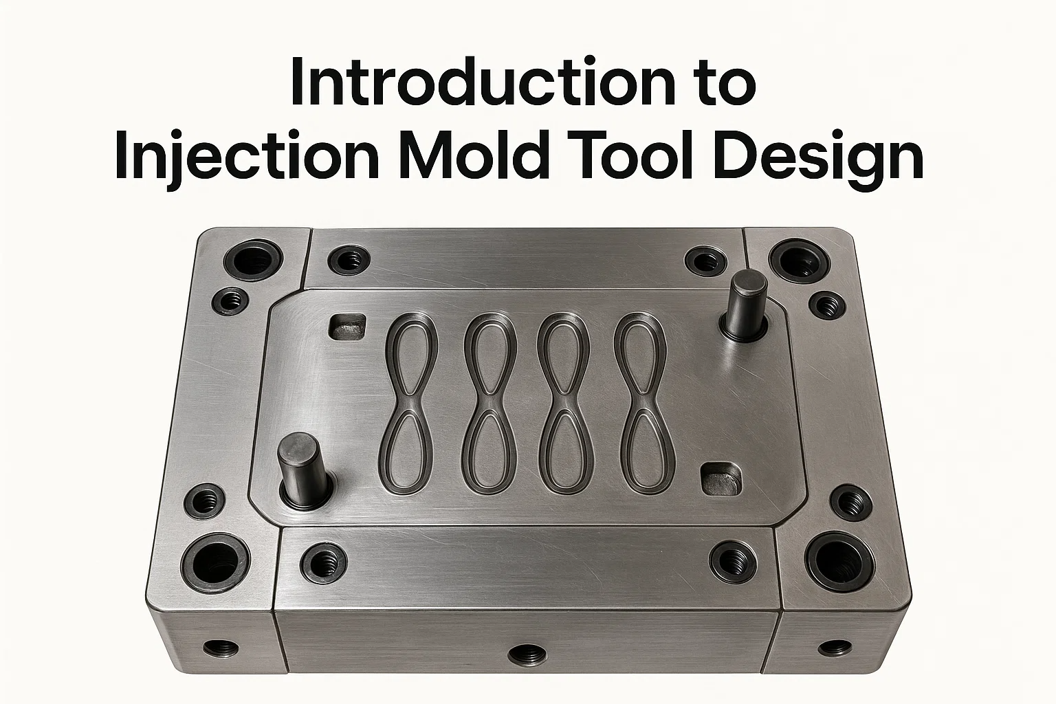
Introduction to Injection Mold Tool Design
If you're in product development or manufacturing, you know the truth: the injection mold tool is the unsung hero of mass production. It’s where your brilliant design meets manufacturing reality, and frankly, it's where cycles are either optimized or hopelessly jammed. The mold isn't just a part of the process—itisthe process.
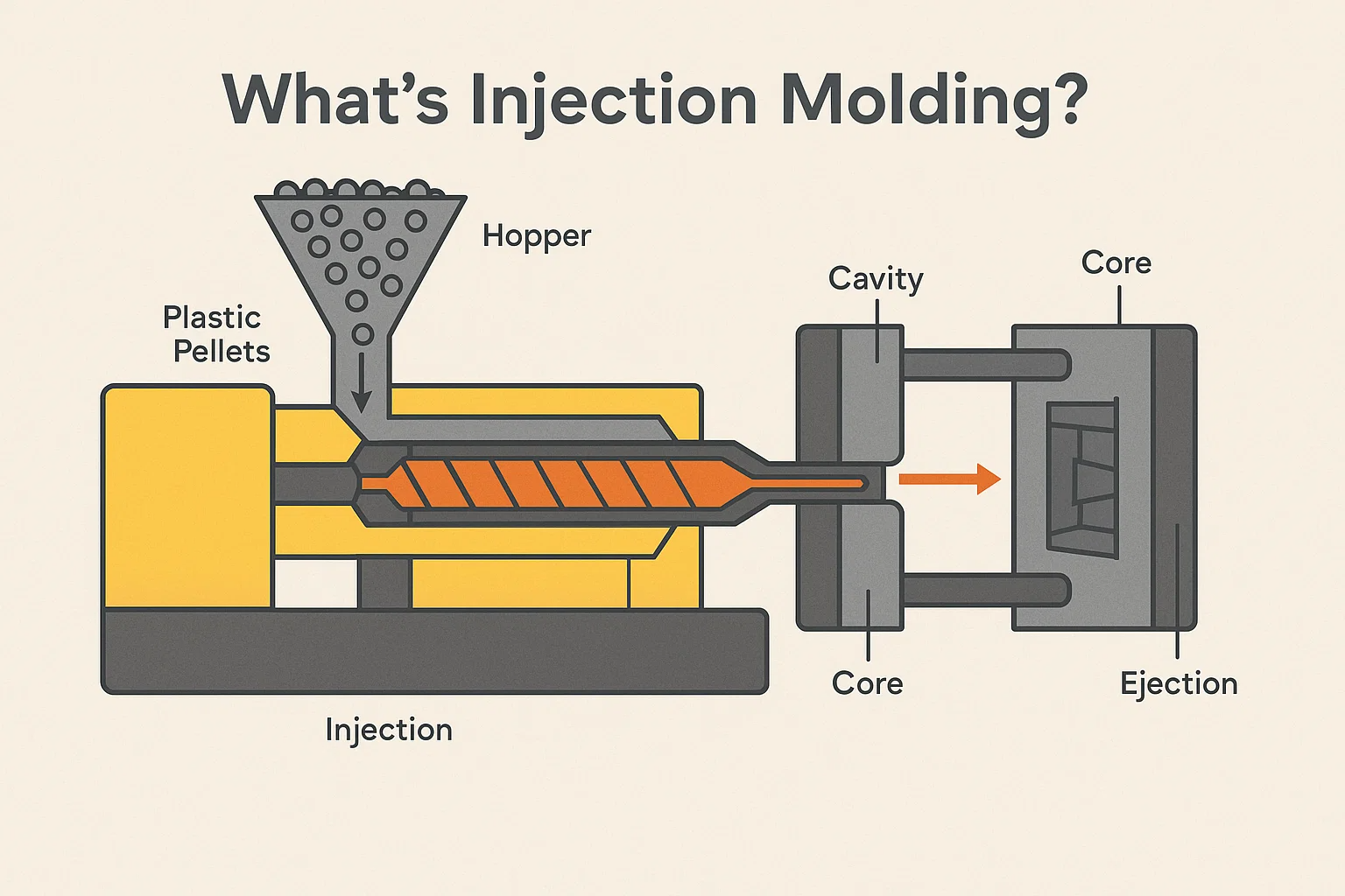
What is Injection Molding?
At its core, injection molding is a sophisticated method for manufacturing plastic parts, from phone cases and bottle caps to automotive dashboards and medical devices. It works by injecting molten plastic material—typically a thermoplastic—into a specially designed, cooled mold cavity. Once the plastic cools and solidifies, the mold opens, and the finished part is ejected.
It’s an incredibly efficient, high-volume process, making it the bedrock of modern manufacturing.
Overview of the Injection Molding Process
To appreciate the mold design, you need to understand the process it supports. It typically involves four steps:
-
Clamping: The two halves of the mold, the cavity and the core, are closed and held tightly together by the molding machine's clamping unit.
-
Injection: Plastic pellets are melted down in a heated barrel and then rapidly injected under high pressure through a gating system into the mold cavity.
-
Cooling: The molten plastic contacts the cooled surfaces of the mold, transferring heat until the part is rigid enough to be handled. This is often the longest part of the entire cycle time.
-
Ejection: The mold opens, and an ejection system pushes the finished part out of the cavity, restarting the cycle.
Importance of Mold Design in Manufacturing
Here’s the thing you need to know: a great part design can be crippled by a poor mold design. The mold tool acts as the inverse of your final product, and its design dictates three critical outcomes:
-
Part Quality: The mold's design controls everything from shrinkage and warpage to surface finish and dimensional accuracy. Flawless parts come from flawless tools.
-
Cycle Time: A tool's cooling channels, runner system, and ejection strategy determine how quickly you can make each part. Optimizing the mold is the fastest path to reducing cost per part.
-
Tool Longevity and Maintenance: The materials chosen (the tool steel) and the design complexity affect how long the mold can run before needing repair. A well-designed mold can produce millions of shots; a poor one might fail after thousands.
Investing the time and expertise in a solid injection mold tool design upfront is the single best way to ensure efficient, high-volume production and avoid expensive, time-consuming troubleshooting down the line. It’s a classic pay now or pay much more later scenario.
Key Principles of Injection Mold Design
Before a single piece of steel is cut, the mold designer must understand the part's geometry and how the molten plastic will behave within the cavity. This is where the crucial design principles come into play. Ignoring these leads directly to quality defects, slow cycles, and high tooling costs.
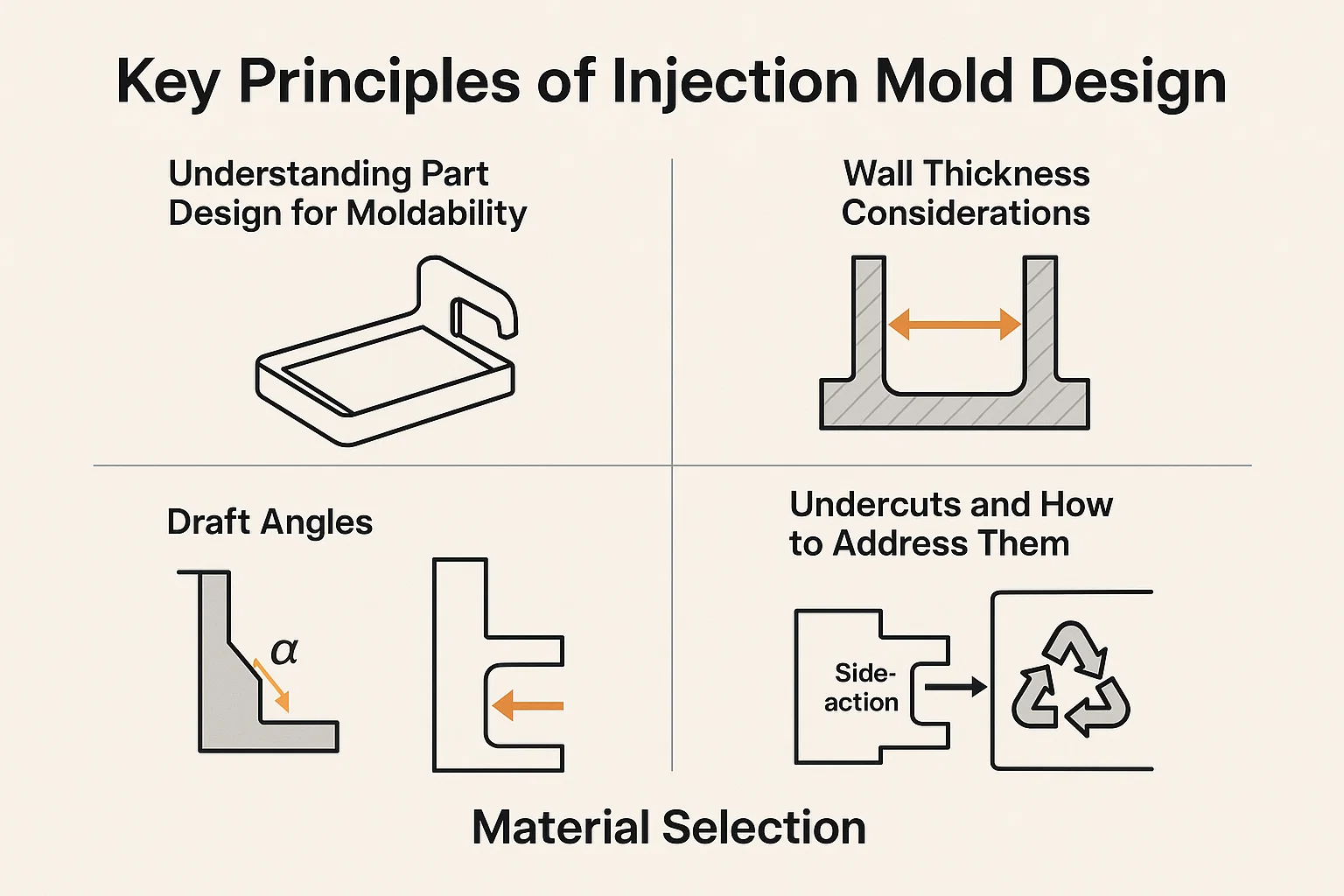
Understanding Part Design for Moldability
The golden rule of injection molding is simple: Design the part for the process. A part that is dimensionally perfect on paper is useless if it can't be molded efficiently.
Wall Thickness Considerations
The thickness of your part's walls is arguably the most critical factor influencing both mold design and cycle time.
-
Uniformity is Key: Aim for uniform wall thickness across the entire part. When thickness varies too much, thin areas solidify faster than thick areas, causing the material to pull unevenly. This results in internal stresses and, inevitably, warpage and sink marks (small depressions where the material pulls inward).
-
The Cooling Challenge: Thick walls require significantly more time to cool down. Doubling the wall thickness can oftenquadruplethe cooling time, dramatically increasing your part cost. Designers must find the sweet spot: thick enough for structural integrity, but thin enough for fast, cost-effective cycles.
Draft Angles
Draft angle is a slight taper added to all vertical walls of the part relative to the mold's opening direction. It is the single best way to ensure the part ejects smoothly without damaging itself or the mold.
-
Minimum Requirement: While specific requirements vary based on material, finish, and wall depth, a minimum draft of to per side is a good starting point. Textured surfaces or very deep parts often require higher draft angles ( or ).
-
Avoid Drag: Without adequate draft, the friction created during ejection can cause the part to drag against the cavity wall, leading to scratches, distortion, or stress marks—a major headache known as "drag."
Undercuts and How to Address Them
An undercut is any feature of the part that prevents it from being pulled straight out of the mold. Think of hooks, clips, threads, or holes perpendicular to the direction of mold opening.
-
The Cost Factor: Undercuts are not strictly forbidden, but they dramatically increase mold complexity, tooling cost, and cycle time.
-
Addressing Undercuts: These features require specialized moving mold components, often called side-actions or core pulls. These mechanisms slideperpendicularto the main mold opening direction to form the undercut feature, retract before the main mold opens, and then slide back in to form the next part. Proper design of these mechanisms is crucial for tool longevity and reliability.
Material Selection
The material you choose is foundational. It dictates the required temperatures, pressures, cooling strategy, and ultimately, the choice of mold tool steel itself.
Common Thermoplastics and Their Properties
Designers primarily use thermoplastics for injection molding because they can be melted and solidified repeatedly. Each family has a critical impact on the mold:
| Material Family | Examples | Key Mold Impact |
| Commodity Plastics | Polyethylene (PE), Polypropylene (PP) | Lower melt temperature, lower pressures, but often high shrinkage rates. |
| Engineering Plastics | ABS, Polycarbonate (PC), Nylon (PA) | Higher melt temperatures and pressures; excellent mechanical properties but demand robust cooling systems and precise tooling. |
| High-Performance Plastics | PEEK, PPS | Extremely high melt temperatures; require specialized, high-hardness tool steels and heating elements. |
Material Compatibility with Mold Design
The two properties that designers care most about are:
-
Melt Flow Index (MFI): How easily the plastic flows. Low MFI materials require higher injection pressure and wider runners and gates.
-
Shrinkage Rate: This is the percentage the plastic will contract after cooling. This ratemustbe compensated for when cutting the mold steel (i.e., the mold cavity is always cut larger than the final part).
Mold Layout and Configuration
The mold tool is much more than just a cavity. It’s a precisely engineered machine built to withstand tons of pressure, manage intense heat, and repeat the cycle millions of times. The configuration decisions made here directly impact the total production cost and flexibility.
Single vs. Multi-Cavity Molds
One of the first decisions is how many parts the mold will produce per cycle:
-
Single-Cavity Molds:
-
Pros: Lower initial tooling cost, faster to build, easier to troubleshoot and maintain, and ideal for low-to-moderate production volumes or for large parts.
-
Cons: Slower overall production rate.
-
-
Multi-Cavity Molds:
-
Pros: Significantly higher production volume, as you can produce 2, 4, 8, 16, or more identical parts in one shot, maximizing machine time.
-
Cons: Much higher tooling cost and complexity. All cavities must fill, cool, and eject simultaneously. Any slight variation between cavities (imbalance) can lead to scrap parts and necessitate expensive mold adjustments.
-
-
Family Molds: A specific type of multi-cavity mold where different, related parts (like a lid and a container) are run in the same tool. These are often complex to balance and are generally avoided unless production volumes are closely matched.
Mold Base Selection
The mold base is the standardized framework—the housing—that holds all the crucial custom components (like the cavity and core plates) in precise alignment. It is the structural backbone of the entire tool.
-
Function: It provides plate strength, channels for guiding pins and screws, and mounting surfaces for the press.
-
Standard vs. Custom: Most designers use standardized mold bases (e.g., from companies like DME or Hasco). This saves time, reduces cost, and ensures components are interchangeable. Only for highly specialized or massive tools is a custom base designed from scratch.
-
Plate Structure: A mold base is composed of several stacked plates. For example, a common two-plate mold includes the cavity plate, the core plate, and the ejector plates. The choice of base dictates how the gating systems (discussed next) will be designed and whether a hot runner system can be incorporated.
Components of an Injection Mold
Whether it’s a simple two-plate mold or a complex stack mold, every injection tool consists of the same core components working together. Understanding these parts is essential for diagnosing issues and designing for reliability.
Mold Base
As mentioned, this is the entire assembled structure that holds the custom components. It includes:
-
A-Side (Cavity Side): The half of the mold attached to the injection nozzle side of the machine.
-
B-Side (Core Side): The half that moves and contains the core, from which the part is typically ejected.
-
Guide Pins and Bushings: These precision components ensure that the A-Side and B-Side plates align perfectly every single time the mold closes.
Cavity and Core
These are the pieces of steel that actually define the part geometry:
-
Cavity Plate (A-Side): Forms the external, or "outside," shape of the molded part.
-
Core Plate (B-Side): Forms the internal features, or "inside," shape of the molded part.
These plates are often made from high-grade tool steel and are machined with extreme precision, as the interface between them determines the part's integrity.
Gating Systems
The gating system is the lifeline of the mold. It must efficiently channel molten plastic from the runner into the cavity while leaving a minimal, easy-to-remove vestige (the small piece of material left where the plastic enters the part).
Types of Gates (Sprue, Runner, Edge, Submarine)
The design of the gate largely dictates the quality of the part, the cycle time, and the post-molding labor required (trimming the vestige).
| Gate Type | Description | Pros | Cons |
| Sprue Gate | Direct injection into the center of the part (only for single-cavity molds). | Excellent pressure transfer; minimal flow path. | Leaves a large vestige; usually only for round/cylindrical parts. |
| Edge Gate | Fills the part along the parting line. Easiest to machine. | Simple, cost-effective, easy to trim manually or robotically. | Leaves a visible witness mark on the side of the part. |
| Submarine (Tunnel) Gate | Cut below the parting line, forcing the gate to shear off as the part is ejected. | Self-degating—no need for manual trimming, saving labor costs. | Requires high shear, which can stress the plastic; only suitable for small gates. |
| Diaphragm/Ring Gate | Used for cylindrical parts; fills the part uniformly around the entire circumference. | Minimizes warpage and weld lines in round parts. | Leaves a large vestige requiring specialized trimming. |
Gate Placement Optimization
Gate placement is a critical decision driven by a single goal: achieve uniform filling and cooling.
-
Thickest Section: Plastic should generally enter the mold at the thickest cross-section of the part. This ensures the rest of the cavity remains pressurized while the thick area cools and shrinks, mitigating sink marks.
-
Flow Distance: Minimize the distance the plastic has to flow to reduce pressure drop and the potential for short shots (unfilled areas).
-
Weld Lines: Avoid placing gates where two flow fronts must meet in a critical area (like near a stress point). Where flow frontsmustmeet, a weld line is formed, which is a structural weakness and a visual defect. Proper gating can push the weld line into a non-critical area.
Ejection Systems
Once the plastic has cooled, the part must be removed efficiently without distortion. The ejection system is the mechanism built into the B-side (core side) of the mold that pushes the part out.
-
Golden Rule: Ejectors must push on the part's strongest features, or where the plastic is still warm and flexible, to avoid punching through the material or deforming the part.
-
Uniform Force: The key is to distribute the ejection force evenly across the surface area.
Pin Ejection
The most common method. Ejector pins are round, hardened steel pins that sit flush with the core plate surface.
-
Mechanism: When the mold opens, the ejector plate moves forward, pushing the pins out and forcing the part off the core.
-
Design: Pin placement must be strategically located, often near thick sections or ribs, and never on sloped surfaces without adequate support, as this can cause the pin to bend or wear the steel.
Sleeve Ejection
Often used for round features like bosses or deep cores.
-
Mechanism: A sleeve (a tube-shaped ejector) fits around the feature it's ejecting, distributing the force over a large, circular area.
-
Benefit: Ideal for parts that must remain visually perfect, as the witness mark left by the sleeve is less noticeable than a small pin mark.
Stripper Plate Ejection
Used for large, box-like, or shallow parts where distributed force is essential to prevent part warpage.
-
Mechanism: A dedicated stripper plate surrounds the part profile. When activated, the entire ring pushes the part off the core evenly around its perimeter.
-
Benefit: Provides the most uniform and gentle ejection, minimizing stress and deformation, especially with softer materials.
Cooling Systems
The cooling system is responsible for up to of the total cycle time. Effective cooling is the single greatest variable in profitable injection molding.
Importance of Cooling in Injection Molding
Poor cooling leads to:
-
Long Cycle Times: Directly increasing the cost per part.
-
Warpage: Uneven cooling causes material to shrink at different rates, leading to internal stresses and non-flat parts.
Cooling Channel Design
The core strategy is to remove heat quickly and uniformly.
-
Conformal Cooling: The gold standard, though expensive. Channels are designed to follow theconformation(shape) of the cavity and core surface, ensuring consistent temperatures.
-
Distance: Channels should be placed close to the cavity surface (typically to times the channel diameter) and adequately spaced from each other.
-
Baffles and Bubblers: For deep, thin core pins that are hard to cool, a baffle (which forces coolant down and up a channel) or a bubbler (which forces coolant tobubbleup an isolated tube) is used to draw heat out from the center of the steel.
Coolant Selection
Water is the most common coolant, but systems often use water mixed with glycol (antifreeze) for temperature control flexibility. The goal is to maximize the turbulent flow of the coolant within the channels, as turbulent flow is significantly more efficient at heat transfer than laminar flow.
Design Considerations for Injection Molds
These final design checks are crucial for ensuring the finished part is structurally sound and meets dimensional tolerances. They often involve anticipating how the plastic will behave under stress and during cooling.
Venting
This is often the most overlooked component that causes the biggest headaches. When plastic rushes into a cavity, it displaces the air inside. If that air can't escape, it causes problems.
Why Venting is Crucial
-
Burn Marks: Trapped air compressed by the incoming plastic can heat up rapidly (adiabatic compression), actually scorching the plastic and leaving black or brown burn marks at the end of the flow path.
-
Short Shots: If air is trapped in the corners, it prevents the plastic from filling the cavity completely, resulting in a short shot—a rejected, incomplete part.
-
Weld Line Strength: Proper venting helps gas escape from areas where flow fronts meet, improving the fusion and strength of the resultant weld lines.
Venting Techniques
Vents are shallow channels machined into the mold's parting line or at the deepest point of the cavity.
-
Parting Line Vents: Most common. Vents are typically 0.0005 to 0.0015 inches deep (the thickness of a human hair) and 0.25 inches wide.They are wide enough for air to escape, but too narrow for the viscous plastic to penetrate.
-
Ejector Pin Vents: Small gaps around ejector pins can also serve as vents.
-
Porous Steel: In complex areas, specially sintered, porous tool steel inserts can be used, allowing air to pass directly through the steel while holding the plastic back.
Shrinkage
All plastic shrinks as it cools. This isn't a defect; it's a certainty. The failure is not accounting for it.
Understanding Material Shrinkage Rates
Every plastic has a published shrinkage rate (a percentage range). For example, Polyethylene (PE) might shrink around 1.5%. while Polycarbonate (PC) might shrink only 0.6%.
-
Factors: The actual shrinkage is affected by mold temperature, pack pressure, and wall thickness. High packing pressure reduces shrinkage, but requires a more robust mold.
Compensating for Shrinkage in Mold Design
The mold tool is always machined larger than the final part. The designer uses the material's nominal shrinkage rate to calculate the required cavity size.
Mold Dimension=Nominal Part Dimension×(1+Shrinkage Rate)
Failure to use the correct shrinkage factor means the parts will be out of tolerance straight off the machine.
Warpage
Warpage is the deformation or distortion of a part, causing it to deviate from its intended flat or straight shape. It's the nemesis of the mold designer.
Causes of Warpage
The root cause is almost always uneven cooling or stress.
-
Differential Cooling: If one side of the part cools faster than the other, the plastic on the faster side solidifies and shrinks first, pulling the rest of the material toward it. This often happens if the cooling channels are too far from one surface.
-
Non-Uniform Wall Thickness: As discussed earlier, thick and thin sections cool at different rates, introducing internal stresses that cause the part to bend when ejected.
Design Techniques to Minimize Warpage
-
Symmetry: Design parts and the mold's cooling system to be as symmetrical as possible to ensure balanced cooling.
-
Ribs and Gussets: Use structural features like ribs to provide support and direct the shrinkage forces into manageable patterns, much like structural beams in a building.
Stress Concentration
Stress concentrations are areas within the part where physical forces build up, making the part prone to cracking or failure, often visible as white stress marks.
Identifying and Mitigating Stress Risers
-
Sharp Corners: Plastic flow doesn't like abrupt changes. Sharp internal corners are massive stress risers and should be replaced with radii wherever possible to allow the material to flow smoothly and distribute stress.
-
Gate Location: Improper gate placement can introduce high shear stress, leading to material degradation and weak points near the gate vestige.
Surface Finish
The surface finish of the part is a direct reflection of the surface finish applied to the mold steel.
Achieving Desired Surface Quality
-
Polish: Standardized finishes are measured by the Society of the Plastics Industry (SPI). A SPI A-1 finish is a high-gloss, mirror polish, while a SPI D-3 is a rough, dull surface.
-
Texturing: Textures (like leather grain or matte finishes) are etched into the steel using chemical processes (often masking and acid). Textures help hide minor flow defects, but require significant draft angles for successful ejection.
Injection Mold Simulation and Analysis
In the past, designing a mold involved a lot of calculated guesswork and costly steel corrections ("cut-and-try"). Today, Mold Flow Analysis (MFA) takes the guesswork out, saving significant time, money, and headaches.
Introduction to Mold Flow Analysis
Mold Flow Analysis is a powerful simulation process that uses computational fluid dynamics (CFD) to predict how molten plastic will flow, pack, and cool within the cavity before the mold even exists. It essentially provides a sneak peek into the first production run.
Benefits of Simulation
The real value of MFA is risk reduction. It allows the designer to:
-
Optimize Gate Location: See the filling pattern in real-time and determine the ideal location to minimize weld lines and reduce flow distance.
-
Predict Defects: Identify potential trouble spots like short shots, air traps, sink marks, and high shear stress areas that could degrade the material.
-
Refine Cooling Strategy: Analyze temperature uniformity and optimize cooling channel placement to minimize cycle time and warpage.
-
Validate Tooling Requirements: Determine the necessary clamping tonnage and injection pressure before the tool is built.
Software Tools for Mold Simulation
A designer relies on specialized software to run these complex calculations. Industry-leading tools include:
-
Autodesk Moldflow: Often considered the industry standard, offering a wide range of analysis capabilities.
-
Solidworks Plastics: Integrated within the popular CAD environment, making it accessible to design engineers.
-
Moldex3D: Known for high-fidelity 3D modeling, especially for complex geometries.
Interpreting Simulation Results
The simulation output is a map of the manufacturing process. Designers look for the "red flags" that indicate a bad design decision.
-
Identifying Potential Issues (e.g., Short Shots, Weld Lines):
-
Short Shots: Look for areas on the final filling time plot that remain unfilled, indicating insufficient pressure or trapped air.
-
Weld Lines: Trace where flow fronts meet. If a weld line is predicted in a high-stress area, the gate must be moved, or a heating element might be needed to improve material fusion.
-
Air Traps: Identify where the air is pushed to the last point of fill; this is exactly where a vent needs to be placed.
-
Temperature Hotspots: Locate areas that retain heat too long, signaling inadequate cooling that will lead to longer cycle times or warpage.
-
Optimizing Mold Design Based on Simulation
The goal is an iterative loop:
-
Analyze: Run the simulation on the current design.
-
Modify: Adjust wall thickness, gate size, runner size, or cooling channel placement in the CAD model.
-
Re-Analyze: Run the simulation again until all critical defects are eliminated and cycle time is minimized.
This disciplined approach ensures that when you finally commit to expensive CNC machining of the steel, you are highly confident the mold will perform right the first time.
Advanced Injection Mold Design Techniques
While a standard cold runner mold is adequate for many parts, modern manufacturing often demands lower scrap, faster cycles, and complex multi-material parts. These advanced systems meet those demands, though they come with a higher tooling investment.
Hot Runner Systems
A hot runner system is a heated manifold assembly that keeps the plastic molten right up to the gate of the cavity. Essentially, the runner system is integrated into the mold, eliminating the cold "runner" waste.
Advantages of Hot Runners
-
Zero Waste: Since the runner material never cools, there is virtually no waste plastic (sprue/runner scrap) to be reground or discarded. This is crucial for expensive engineering resins.
-
Reduced Cycle Time: The molding machine doesn't have to wait for the thick runner system to cool, which can significantly shave seconds off the cycle.
-
Automation: Parts drop cleanly with no attached runner, simplifying automation and packaging.
-
Better Part Quality: Hot runners allow for more controlled pressure and packing, leading to reduced stress and better part uniformity.
Hot Runner Design Considerations
-
Cost: Initial tooling cost is significantly higher than a cold runner mold.
-
Maintenance: More complex components (heaters, thermocouples, valve gates) require specialized maintenance and troubleshooting.
-
Valve Gates: For the best control, valve gate systems are often used. These physically open and close a pin at the gate location, offering precise control over material flow and leaving a cleaner vestige.
Gas-Assisted Injection Molding
This technique is designed for parts with thick sections or large structural components that are prone to sink marks and warpage.
-
Process: After the cavity is partially filled with plastic, an inert gas (usually nitrogen) is injected under high pressure into the thickest core section.
-
Benefit: The gas core-out the thick section, pushing the plastic against the mold walls until it cools. This reduces material usage, eliminates sink marks, and minimizes warpage by applying uniform packing pressure from the inside out.
Multi-Component Injection Molding (2K Molding)
This technique creates a single part using two or more different materials or colors in sequence, often without removing the part from the mold.
-
Process: The mold incorporates a rotating core or a shuttle system. The first material (M1) is injected. The mold then opens, the core rotates (or shuttles), and the second material (M2) is injected into or around the first shot.
-
Applications: Keypads, tool handles (hard plastic structure with a soft-touch elastomer grip), or lenses with integrated seals.
Overmolding
Similar to multi-component molding, but usually involves molding a second material (often a thermoplastic elastomer or TPE) over a pre-existing substrate or insert.
-
Process: A finished plastic or metal component is manually or robotically placed into the mold cavity, and the second material is injectedoverit.
-
Applications: Adding soft-grip surfaces to electronic devices, encasing metal components, or creating watertight seals. The key design challenge is ensuring the second material achieves a robust adhesion to the first.
Materials for Injection Molds
The mold material is where all the pressure, heat, and friction of the molding cycle are absorbed. The right choice is a trade-off between hardness (for wear resistance) and machinability (for cost).
Tool Steels
Tool steel is the backbone of high-volume injection molding. They are high-carbon alloys designed to offer a balance of hardness, toughness, and thermal stability.
Common Types of Tool Steels (e.g., P20, H13, S7)
| Tool Steel Type | Key Characteristics | Typical Application |
| P20 | Pre-hardened; easy to machine; good polishability. | Low to medium volume molds (up to 500k shots); general-purpose. |
| H13 | Highly heat-resistant (hot work steel); excellent toughness; often used for hot runner components. | High-temperature engineering plastics (e.g., Nylon, PEEK); often used for cores and cavities. |
| S7 | Excellent shock resistance (high toughness); good for intricate features. | High-impact materials; often used for structural components or side-actions. |
| Stainless Steel (e.g., 420 SS) | Corrosion resistance is critical. | Molds for corrosive resins (e.g., PVC) or medical/food-grade applications that require cleanroom environments. |
Factors Affecting Steel Selection
The choice is driven by three main factors:
-
Production Volume: High volumes (millions of shots) demand high-hardness steel (like H13 or D2) to resist wear. Lower volumes allow for softer, cheaper, and faster-machining steel like P20.
-
Abrasiveness of Resin: Resins filled with glass fibers or minerals are highly abrasive and quickly erode soft steel, necessitating hardened materials.
-
Corrosive Resins: Materials like PVC or those that release corrosive gases require stainless steel.
Aluminum
While not a steel, aluminum alloys are a common choice, especially for prototype and low-volume tooling.
-
Advantages: Excellent thermal conductivity (can cool up to five times faster than steel), making cycle times very fast. Much easier and quicker to machine than steel.
-
Disadvantages: Softer than steel, meaning they wear out faster and are more susceptible to damage from high pressures or abrasive resins.
-
Application: Ideal for soft tooling or bridge tooling where quick production is paramount.
Other Materials (e.g., Beryllium Copper)
These specialized alloys are used strategically:
-
Beryllium Copper (BeCu): Often used as inserts in high-heat areas of a steel mold (e.g., near the gate or at deep core pins). BeCu offers thermal conductivity superior to steel, accelerating the cooling of localized hotspots and balancing the mold's temperature profile.
Manufacturing Injection Molds
Once the steel is selected, the physical construction begins. The mold tool is arguably the most complex and precise component in a manufacturing line, relying on highly specialized techniques.
Machining Processes
The geometry of the cavity and core must be translated from the digital CAD file into hardened steel with micron-level precision.
-
CNC Machining: Computer Numerical Control (CNC) milling is the primary method for bulk material removal and cutting the main features like the mold base and runners. High-speed, 5-axis CNC machines are essential for cutting complex 3D contours.
-
EDM (Electrical Discharge Machining): This is a non-contact, thermal erosion process critical for features that milling cutters cannot reach. It's used to create:
-
Sharp Internal Corners: EDM can burn perfectly sharp internal corners that a rotating end mill cannot produce due to its radius.
-
Deep, Fine Ribs: It creates deep, thin features without chatter or breaking.
-
-
Grinding: Used for finishing critical surfaces like shut-off areas (where the cavity and core meet) and for precisely sizing components like guide pins and ejector sleeves.
Mold Assembly and Testing
Machined components are meticulously assembled. Guide pins are installed, cooling lines are pressure-tested, and the ejection system is checked for smooth movement.
-
Tool Tryout: The assembled mold is placed into an injection molding machine for a tool tryout. This is the first run, where settings are dialed in and the initial plastic parts (the "first shots") are produced and measured. This crucial step verifies all the work done in the design and simulation stages.
Maintenance and Repair of Injection Molds
A high-performance mold is a high-performance asset. Treating it as such is essential for minimizing long-term costs.
Preventive Maintenance
Scheduled maintenance is non-negotiable for longevity. It typically involves:
-
Cleaning: Removing gas residue and plastic buildup.
-
Lubrication: Ensuring all moving components (pins, side-actions) are correctly lubricated.
-
Inspection: Checking for cracks, wear on the parting line, and corrosion in the cooling channels.
Troubleshooting Common Mold Issues
Mold makers often diagnose issues based on part defects:
-
Flash: Plastic squeezing out at the parting line indicates insufficient clamping force or wear on the shut-off surfaces, requiring polishing or repair.
-
Weld Line Failure: Suggests the gate is poorly placed, or the material needs higher temperature/pressure (packing).
-
Burn Marks: Indicates poor venting that needs to be addressed.
Repair Techniques
Common repairs include welding (often laser welding for precision) to fix damaged edges or using EDM to adjust critical dimensions.
Fantastic. We've covered the design, the analysis, the advanced systems, and the manufacturing process. The final step is looking forward—where is this industry going?
Future Trends in Injection Mold Design
Injection mold tool design is not static. New technologies are constantly evolving, driven by the demand for faster prototyping, cheaper custom parts, and smarter manufacturing. These trends are redefining the role of the mold designer.
Additive Manufacturing for Mold Inserts
While you won't 3D-print a massive mold base, Additive Manufacturing (AM), or 3D printing, is revolutionizing internal components, specifically the core and cavity inserts.
-
Conformal Cooling: The biggest game-changer. AM allows designers to create complex, internal cooling channels that precisely follow the contour of the part. These channels are impossible to machine conventionally, but they ensure incredibly uniform cooling, drastically reducing warpage and cutting cycle times by up to in some cases.
-
Rapid Prototyping Inserts: AM enables the creation of low-cost, low-volume inserts for soft tooling, allowing designers to rapidly test design variations (A/B testing) before committing to expensive tool steel.
Smart Molds with Sensors
The next generation of molds won't just make parts; they'll talk to the machine and to the cloud. Smart Molds use integrated sensors to provide real-time process data.
-
Cavity Pressure Sensors: These small sensors placed inside the cavity measure the exact pressure the plastic is exerting as it fills and packs. This is crucial for precise quality control, allowing the machine to adjust injection speed or packing pressure mid-cycle to ensure every part is consistent.
-
Temperature Sensors (Thermocouples): Placed throughout the cavity and core, these monitor steel temperature, providing live feedback to the cooling unit to ensure optimal, balanced cooling—the ultimate weapon against warpage.
-
RFID/Data Chips: Used for instant mold recognition by the molding machine, automatically loading the correct process parameters, maintenance history, and shot count. This eliminates human error during mold setup.
Automation in Mold Design and Manufacturing
Efficiency in tool building is increasing through more integrated digital workflows.
-
Design Automation: Advanced CAD/CAM systems are using artificial intelligence and rule-based design to automate repetitive tasks, such as generating draft angles, placing standard ejector pins, and routing cooling channels. This frees the experienced designer to focus on complex, high-value problem areas.
-
Robotics in Tool Manufacturing: Precision robots are increasingly used alongside CNC machining and EDM processes for automated electrode changing and material handling, minimizing human interaction and increasing the accuracy and consistency of the final tool.
Conclusion
Recap of Key Design Principles
Injection mold tool design is a complex balancing act, an intersection of physics, materials science, and meticulous engineering. To create a successful tool—one that runs reliably and profitably—you must master the fundamentals:
-
Moldability: Prioritize uniform wall thickness and incorporate sufficient draft angles.
-
Efficiency: Optimize the gating system and design robust, balanced cooling channels to minimize cycle time.
-
Reliability: Compensate precisely for shrinkage and ensure adequate venting to prevent burn marks and short shots.
Importance of Continuous Learning in Mold Design
The reality is, mold design is an apprenticeship that never truly ends. With new materials, higher performance demands, and emerging technologies like conformal cooling and smart molds, continuous education isn't optional—it’s necessary to remain competitive.

