 English
 Indonesia

Injection mold performance depends on much more than the final mold assembly. Every component—from the core and cavity inserts to the cooling channels, runner system, and ejector mechanism—must be fabricated with the correct material, tolerance, surface finish, and alignment. A small error in one component can lead to flash, warpage, poor surface appearance, short mold life, or repeated mold trials.
For American manufacturers and product developers, understanding the fabrication process behind injection mold parts can make design reviews, supplier selection, and tooling cost evaluation much easier. The following guide explains how key injection mold components are manufactured and what factors influence their reliability.
Core and Cavity Components: From Steel Block to Precision Mold Halves
The core and cavity are the primary mold components that create the final shape of the plastic part. Their fabrication usually starts with a steel block selected according to the expected production volume, plastic material, surface requirements, and maintenance plan.
Common mold steels include P20 for general-purpose tooling, H13 for high-temperature or high-wear applications, and S136 stainless mold steel when corrosion resistance and high-quality polishing are required. The steel block is first rough-machined to remove excess material and establish reference surfaces. CNC milling then creates the main three-dimensional geometry, including ribs, bosses, steps, and parting features.
When the design contains deep cavities, sharp corners, narrow slots, or hardened steel sections, EDM becomes an important part of the process. Sinker EDM can form details that are difficult to cut with conventional tools, while wire EDM is commonly used for precise through-features, inserts, shutoffs, and intricate profiles. Grinding is used afterward to improve flatness, parallelism, and dimensional accuracy.
Heat treatment may be carried out before or after certain machining stages, depending on the steel grade and tooling strategy. Hardened components often require finish milling, EDM, and precision grinding after heat treatment because the steel can distort slightly during the process.
Surface finishing also affects both appearance and part release. Polishing can produce a high-gloss finish, while chemical texturing creates a controlled grain or matte appearance. Treatments such as nitriding, hard chrome plating, and DLC coating may be considered for wear resistance, corrosion protection, or easier demolding. The right choice depends on the resin, production volume, mold temperature, and required cosmetic finish.
Design for manufacturability is essential at this stage. Adequate draft angles reduce the risk of scuffing during ejection. Uniform wall thickness helps reduce shrinkage and warpage, while undercuts may require slides, lifters, collapsible cores, or separately machined inserts. These design decisions directly influence machining time, mold complexity, maintenance cost, and the number of required mold trials.
Mold Base, Plates, and Guiding Elements: Structure, Alignment, and Fabrication
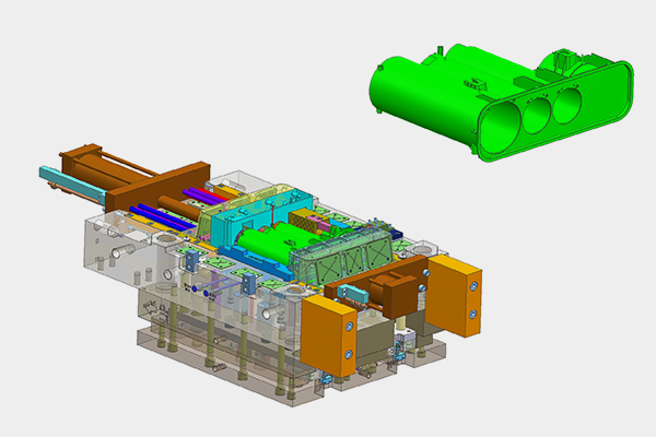
The mold base supports the core and cavity and provides the structure required for clamping, guiding, cooling, and ejection. It normally includes the A plate, B plate, support plate, clamping plates, ejector plates, spacer blocks, guide pillars, and guide bushings.
Standard mold bases from suppliers such as DME and HASCO can reduce lead time and simplify the replacement of standard components. A custom mold base may be selected when the mold has unusual dimensions, complex slide systems, large inserts, special cooling requirements, or a non-standard injection machine layout.
Fabrication begins with sawing, milling, and surface grinding the plates to establish accurate thickness and parallelism. Coordinate boring or CNC machining is then used to produce insert pockets, guide pillar holes, ejector holes, and other reference features. Wire EDM may be used when a particularly accurate profile or hardened component is required.
Correct guiding is essential for protecting the parting line and maintaining consistent alignment. Guide pillar and guide bushing holes must be machined from reliable datum surfaces, with their position, perpendicularity, and fit carefully inspected. Depending on the mold design, the guiding system may use a close sliding fit, a preloaded system, or a manufacturer-specific standard tolerance rather than one universal fit for every mold.
During assembly, technicians check plate parallelism, guide movement, insert seating, and the relationship between the core and cavity. Blueing or red-lead contact checks can reveal incomplete contact on the parting surface. Dial indicators, height gauges, CMM equipment, and optical inspection systems may also be used to verify alignment.
Wear components should be inspected according to production conditions rather than replaced only by calendar date. As a practical reference, guide bushings may receive a detailed inspection around 100,000 molding cycles, while high-load or abrasive applications may require earlier checks. Lubrication, contamination removal, and checking for looseness are often more important than a fixed replacement interval.
Runner, Gate, and Sprue System Components: Flow Path Fabrication and Optimization
The runner and gate system controls how molten plastic travels from the injection machine nozzle to the mold cavity. Its components include the sprue bushing, runners, gates, hot runner manifold, and hot nozzle tips.
The sprue bushing is commonly produced by turning the external profile, drilling the central passage, and grinding or polishing the internal taper. The nozzle contact area must match the injection machine nozzle correctly to prevent leakage and pressure loss.
Cold runners are typically machined into the mold plates or inserts by CNC milling. When the runner contains complex intersections, sharp transitions, or hardened steel details, sinker EDM may be used. Pin gates, submarine gates, and other small gate features can be produced using precision milling, drilling, EDM, or wire EDM, depending on their geometry and tolerance requirements.
Hot runner systems require additional fabrication and assembly work. The manifold must contain accurately machined flow passages, heater pockets, thermocouple locations, and sealing features. Hot nozzle components may use materials such as H13 or SKD61 because they must withstand elevated temperatures, pressure, and repeated thermal cycling. Heater coils, insulation, sensors, and nozzle tips must be installed in the correct position to maintain stable temperature control.
Runner surface finish influences flow resistance, residence time, and material changeover performance. A smoother flow path may reduce material hang-up, but the ideal finish is not always a mirror polish. The design should consider the resin, filler content, gate size, shear sensitivity, and cosmetic requirements.
For manufacturers processing multiple colors or engineering materials, maintainability is an important design consideration. Replaceable gate inserts, accessible manifold components, removable hot tips, and minimized dead zones can make color changes and material switching faster. These features may increase initial tooling cost but can reduce downtime and cleaning labor over the mold's service life.
Ejector Mechanism, Venting, and Parting Line: Detailing and Demolding
The ejector system removes the molded part from the core after the mold opens. Typical components include ejector pins, ejector sleeves, ejector plates, return pins, springs, and guide elements.
Ejector holes must be accurately machined and aligned with the ejector plate. Depending on the mold structure and material condition, CNC drilling, reaming, grinding, or wire EDM may be used. The pin-to-hole relationship must provide smooth movement without excessive clearance that could allow plastic flash to form. A specific fit such as H7/g6 may be used in some tooling designs, but the final fit should be selected according to pin diameter, mold steel, operating temperature, lubrication, and the required sealing condition.
The ejector plates must move evenly and return completely before the mold closes. Ejector plate guide pillars and bushings help prevent binding, while return pins protect the mold from closing with the ejector system out of position. Surface treatments such as nitriding or PVD coatings may extend the life of ejector pins in abrasive or high-cycle applications.
Venting is equally important. Small venting grooves allow trapped air and gases to escape as the cavity fills. Vent depth is resin-dependent, but a common starting range for some thermoplastics is approximately 0.02–0.05 mm. The final value must be validated because excessive depth can cause flash, while insufficient depth can lead to burns, short shots, weld-line weakness, or filling problems.
The parting surface is normally milled and then carefully fitted or ground. Red-lead or blueing checks help confirm that the core and cavity contact correctly around the sealing areas. Ejector pins should be cleaned and inspected regularly, with a detailed check often scheduled around 50,000 cycles as a reference for standard production molds. Abrasive materials, poor lubrication, or high mold temperatures can require shorter intervals.
Cooling System Components: Drilling, Baffles, and Conformal Cooling Fabrication
The cooling system directly affects cycle time, dimensional stability, surface quality, and warpage. Traditional cooling channels are usually manufactured by drilling straight passages through the mold plates or inserts. Deep-hole drilling, angled drilling, plugs, O-ring grooves, and threaded water connections are then used to create complete circuits.
Baffles and bubblers increase the cooling area in deep cores or narrow sections. These components may be machined separately and installed inside drilled passages. Water traps, plugs, seals, and connectors must be designed for reliable maintenance because leaks inside a mold can damage steel, sensors, and electrical components.
Cooling channel layouts should be developed with the part geometry, wall thickness, resin, expected cycle time, and mold-flow analysis in mind. Channels placed too far from the molding surface may provide insufficient cooling, while channels placed too close can weaken the insert or create uneven temperature distribution.
Conformal cooling uses channels that follow the shape of the molded part more closely than conventional straight drilling allows. A common approach is to manufacture a cooling insert using metal additive manufacturing, such as laser powder bed fusion. Materials including maraging steel and other mold-grade alloys may be selected depending on strength, corrosion resistance, and heat-treatment requirements.
After additive manufacturing, the insert normally requires heat treatment, support removal, machining of reference surfaces, sealing checks, and sometimes polishing or coating. Conformal cooling can be valuable for deep ribs, curved surfaces, thin walls, and parts with severe warpage risk. However, it may not be economical for every project. The expected cycle-time reduction, tooling volume, part value, and maintenance requirements should be evaluated before choosing this method.
Cooling channels also require maintenance. Water quality, corrosion, and mineral deposits can gradually reduce heat-transfer efficiency. A cleaning inspection around every 10,000 cycles may be used as a starting reference for demanding production environments, although actual timing depends on water treatment and operating conditions.
From Mold Component Fabrication to Reliable Production Tooling
A successful injection mold is the result of coordinated decisions across material selection, machining, heat treatment, surface finishing, assembly, and validation. At IMTEC Mould, every project can be reviewed from both a manufacturing and production perspective to help reduce unnecessary mold trials, avoid late design changes, and improve delivery confidence.
If you are developing a new plastic component or need support with an existing mold design, contact IMTEC Mould for a tooling consultation. Our team can review core and cavity construction, cooling strategy, ejection, runner design, steel selection, and critical tolerances before fabrication begins.
Discuss Your Injection Mold Project with IMTEC Mould
Frequently Asked Questions
How are core and cavity inserts fabricated in injection mold making?
They are usually rough-machined from mold steel, followed by CNC milling, EDM, wire EDM, grinding, heat treatment, and surface finishing. The exact sequence depends on the steel grade, geometry, hardness, and required tolerance.
What is the difference between hot runner and cold runner mold parts?
Cold runner components are machined into the mold plates or inserts and solidify with the molded part. Hot runner components use heated manifolds and nozzles to keep the plastic molten, requiring additional heater, sensor, sealing, and temperature-control features.
How often should ejector pins and guide bushings be inspected?
Inspection intervals depend on cycle count, resin abrasiveness, mold temperature, lubrication, and operating conditions. As general references, ejector pins may receive a detailed inspection around 50,000 cycles and guide bushings around 100,000 cycles, but these are not universal replacement rules.
What surface coatings are applied to injection mold components?
Common options include nitriding, hard chrome, DLC, and PVD coatings. The appropriate coating depends on wear, corrosion, polishing, resin type, filler content, and the expected production volume.
How are conformal cooling channels manufactured?
They are commonly produced inside metal additive-manufactured inserts using laser powder bed fusion. The inserts still require heat treatment, machining, sealing inspection, and integration into the mold.
What quality control steps are used during mold assembly?
Typical checks include plate flatness, parallelism, guide movement, insert seating, parting-line contact, ejector movement, water-circuit pressure testing, dimensional inspection, and trial molding.
How does tool steel selection affect mold fabrication and service life?
Steel selection influences machinability, hardness, polishing performance, corrosion resistance, wear resistance, heat-treatment distortion, and maintenance requirements. P20, H13, S136, and other grades should be selected according to the application rather than by price alone.


