 English
 Indonesia
Demystifying the Parting Line in Injection Molding: Design Guide & Best Practices
"Novice engineers treat the parting line as an aesthetic afterthought. On the shop floor, a misjudged parting line means paying $3,000 in tool maintenance every 100,000 shots."
1. Introduction
Look at the plastic casing of your mouse, the cap of a water bottle, or the bezel of your monitor. Run your fingernail along the edge, and you will eventually hit a faint, continuous ridge.
That is the parting line (often referred to in quality control as the witness mark).
In plastic injection molding, the parting line is not a defect—it is a physical inevitability. It marks the exact anatomical equator where the two halves of an injection mold separate to release the finished part. However, while the line itself is unavoidable, its location, thickness, and impact on your unit economics are entirely within your control.
For industrial designers, placing it wrong ruins the exterior "hero shot" of a product. For mechanical engineers, placing it wrong guarantees tool binding, excessive flash, and blown-out tolerances. This guide will walk you through the engineering realities of parting line placement, backed by IMTEC Mould's actual shop-floor data.
2. What is a Parting Line in Injection Molding?
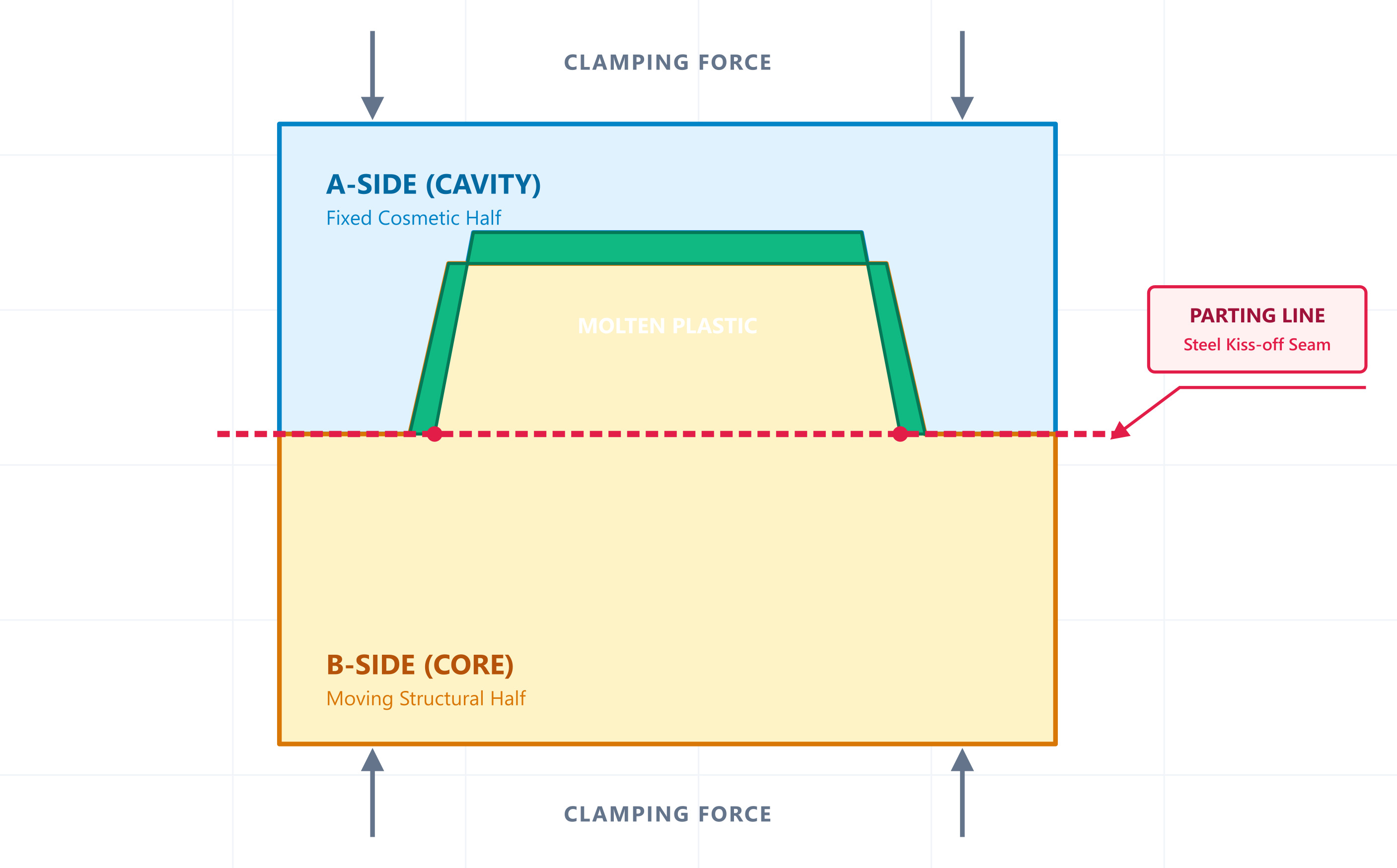
To understand the line, you have to look inside the tool. An injection mold fundamentally consists of two massive blocks of machined tool steel:
- The A-Side (Cavity): The concave half that forms the exterior, cosmetic "skin" of the part.
- The B-Side (Core): The convex half that forms the internal, structural geometry (ribs, bosses, and snap-fits).
When the injection molding machine's clamping unit slams these two halves together under hundreds of tons of force, molten thermoplastic is shot into the void between them. The microscopic seam where the steel faces of the Core and Cavity kiss is the parting line.
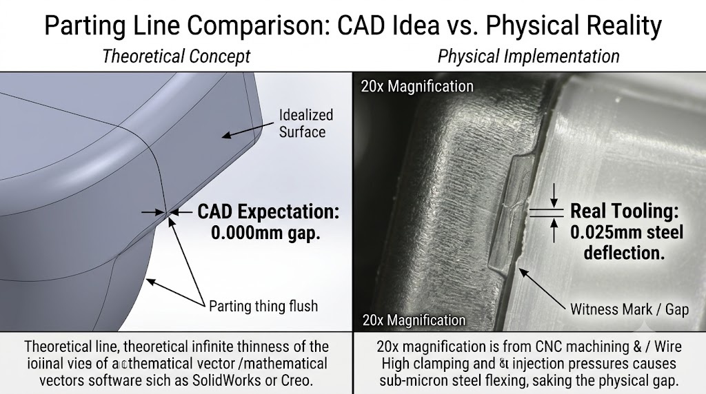
The CAD Ideal vs. The Shop Floor Reality
In software like SolidWorks, Creo, or NX, a parting line is a vector—an infinitely thin mathematical concept. In a real molding facility, a parting line is a physical gap.
Even the highest-grade 5-axis CNC milling machines and Wire-EDMs leave a microscopic surface roughness. When 150 tons of clamping pressure meet 20,000 PSI of internal cavity injection pressure, the steel flexes at a sub-micron level. The "witness mark" you see on the plastic is the molten polymer attempting, and failing, to squeeze into that flexing steel seam.
3. Why the Parting Line Location Matters
If you leave the parting line placement entirely to your tooling supplier's default CAD script, you are exposing your project to severe budget creep. The placement dictates four major project pillars:
A. The "A-Surface" Trap (Cosmetics)
Consumers subconsciously equate visible seams with cheap manufacturing. If a parting line runs right across the primary touchpoint or the front display face of a handheld device, no amount of high-gloss polishing will save the product's perceived quality.
B. Tolerance Stacking Across Boundaries
Dimensions measured across a parting line (spanning from a Core feature to a Cavity feature) are inherently less stable than dimensions contained entirely within a single piece of steel. Every time the mold opens and closes, thermal expansion, mechanical wear, and clamping variations introduce a ±0.05mm to ±0.1mm floating variable across that boundary.
C. The Real Cost of Tooling Complexity
To prove this point, the engineering team at IMTEC Mould audited the quoting and DFM data across 145 custom injection molds delivered to our international clients over the last 24 months. Look at what happens to your tooling invoice the moment your parting line stops being a simple flat plane:
| Parting Line Geometry | Tooling Cost Multiplier | Avg. Lead Time Impact | Primary Machining Driver |
|---|---|---|---|
| Flat (Planar) | 1.0x (Base Cost) | Standard (20-25 Days) | High-speed 3-Axis CNC |
| Stepped | + 18.5% Avg. | + 4 Days | Secondary Wire-EDM setups |
| Profiled / Curved | + 34.2% Avg. | + 8 Days | 5-Axis CNC & custom benching |
D. Draft Angles & The "Continental Divide"
The parting line acts as the strict geographic equator for your part's draft angles. All walls above the line must draft inward toward the Cavity; all walls below the line must draft inward toward the Core. If your parting line jumps up and down, your draft vectors must flip accordingly, creating complex interlocking geometries that complicate part ejection.
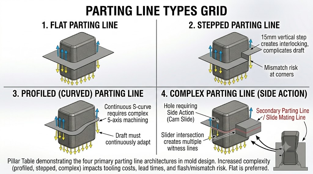
4. Types of Parting Lines
Depending on your part’s geometry, an IMTEC toolmaker will utilize one of four primary parting line architectures. We map these against our internal Shop Floor Headache Matrix to help clients assess risk during the quoting phase:
| Type | Geometry Description | Long-Term Flash Risk | Shop Floor "Headache Level" |
|---|---|---|---|
| 1. Flat | Lies entirely on a single horizontal 2D plane. | Very Low | ⭐ (Effortless) |
| 2. Stepped | Jumps parallel planes via a sharp 90° vertical step. | Medium | ⭐⭐⭐ (Requires tight EDM shut-offs) |
| 3. Profiled | Sweeps along a continuous, organic 3D curve. | High | ⭐⭐⭐⭐ (Requires 5-axis surface matching) |
| 4. Complex | Intersects with Side-Actions, Sliders, or Lifters. | Severe | ⭐⭐⭐⭐⭐ (The Silent Margin Killer) |
5. How to Determine Placement: The IMTEC "C.A.F.E." Protocol
When IMTEC Mould's DFM engineers open an incoming customer `.STEP` file, we ignore the CAD software's automated "Split Line" tool. Automated algorithms find the *geometric* center; we need to find the *manufacturable* center. We filter every part through our internal C.A.F.E. Protocol:
- C – Cosmetics: Does the proposed line cross the "Hero Face" of the device? If so, can we push it to a bottom chamfer or hide it inside an intended cosmetic groove?
- A – Assembly: Does the line intersect a mating snap-fit hook or run down the center of an O-ring groove? Rule of thumb: Never allow a parting line to bisect a dynamic seal.
- F – Function: Will a human hand tightly grip this exact area? A sharp parting line on the handle of a heavy handheld scanner will cause operator blisters within an hour of use.
- E – Ease of Machining: Can a standard 3-axis ball-nose end mill reach every coordinate on this line, or are we forcing the tool shop to burn expensive, slow copper sinker-EDM electrodes?
6. Troubleshooting Parting Line Defects
When tooling failures occur at the parting plane, they typically manifest in one of three classic modes:
1. Flash (The "Bleeding" Tool)
Flash happens when molten polymer escapes the cavity and solidifies inside the microscopic gap between the parting surfaces.
- The Rookie Operator's Diagnosis: "The press clamping tonnage is set too low."
- The IMTEC Master Toolmaker's Diagnosis: Check your material's Melt Flow Index (MFI). A thick, stiff polymer like Polycarbonate (PC) won't flash even with a 0.03mm tool gap. However, if you inject a super-fluid material like **Nylon (PA66)** or **Liquid Silicone Rubber (LSR)** into that exact same mold, it will bleed everywhere. Steel shut-off tolerances must be ground to match the specific melt viscosity of the resin, not just the tonnage of the machine.
2. Parting Line Mismatch (Core/Cavity Shift)
Mismatch occurs when the A-side and B-side misalign laterally by a fraction of a millimeter, turning what should be a smooth flush seam into a tiny, sharp step. This is caused by worn guide pins, asymmetrical thermal expansion of the steel blocks, or core deflection caused by injecting heavy plastic too fast from a single gate.
The 0.08mm Shift That Drowned an IP67 Enclosure
A European tier-1 client approached IMTEC Mould with an outdoor marine sensor housing that was consistently failing static 1-meter water submersion tests at a 40% failure rate.
The Flaw: Their original product designer placed the parting line directly through the geometric center of the radial O-ring sealing groove. Because the production tool had a minor 0.08mm mismatch shift, the rubber O-ring was trying to compress against a microscopic "step". Water squeezed past the step instantly under static pressure.
The IMTEC Fix: We refused to scrap their $25,000 tool. Instead, our machinists re-cut the Core to drop the parting line down by 1.5mm, placing it on the flat, straight outer wall strictly *below* the O-ring track. The O-ring now sealed against a 100% seamless, continuous cylinder of solid steel. The submersion pass rate instantly jumped to 100%.
7. Shop Floor PUA: 3 Parting Line Myths Debunked
If you spend enough time in design agencies or talking to legacy mold makers, you will inevitably be fed one of these three dangerous pieces of tooling mythology:
Myth 1: "Put the parting line right on the tangent of the rounded corner; it hides it better."
The Truth: If you place a parting split at the absolute tangent point of a heavy radius, the two steel halves meeting at that point form a razor-thin "feather edge". Under the repetitive impact of 150-ton clamping cycles, that paper-thin steel tip will fatigue, roll over, and start generating jagged, un-repairable flash within 15,000 shots. Always place the split on the flat plane at least 0.5mm *past* the radius.
Myth 2: "Don't worry about a little flash; the assembly workers can just hand-trim it with a knife."
The Truth: Manual post-processing destroys your unit margin. If an operator takes 12 seconds to carefully scrape the flash off a part, and your annual volume is 200,000 units, you just purchased 666 hours of pure manual labor. That labor will cost you vastly more than paying IMTEC to CNC-grind the shut-off flat in the first place. Furthermore, hand-trimming introduces an uncontrollable 5% cosmetic scrap rate from slipping deburring blades.
Myth 3: "High-gloss finishes hide witness marks better than textured ones."
The Truth: The opposite is true. A mirror-polished SPI-A1 surface acts as a literal reflector; the moment a straight parting line slightly distorts the reflection of the overhead room lights, the human eye detects it instantly. If your product has an ugly, unavoidable parting line across a visible face, specify a chaotic, heavy sandblast texture like **VDI 34** or **SPI-C1** across the boundary. The micro-shadows cast by the heavy texture will naturally scramble and camouflage the witness line.
8. Conclusion: Your Next DFM Step With IMTEC Mould
Drawing a parting line on a CAD monitor takes three seconds; moving a poorly planned parting line inside a 1,200-pound block of hardened P20 tool steel takes three weeks and $5,000.
The ultimate cheat code in plastic manufacturing is radical, early transparency between the product designer and the mold maker.
Stop Guesswork Before You Cut Steel.
Upload your 3D raw CAD geometry (.STEP / .IGES / .X_T) directly to IMTEC Mould. Our tooling engineers will run a full C.A.F.E. Parting Line & Draft Audit on your part and return a manufacturability report within 24 hours—zero cost, zero obligation.
Request Free DFM Analysis →
