 English
 Indonesia
How Does 5-Axis Cutting Transform Modern Mold Design?
Mold design has transitioned from restrictive 2D blueprints to high-precision 5-axis CNC cutting, a shift that allows manufacturers to create complex, organic geometries with a single setup. By utilizing simultaneous multi-axis movement, 5-axis technology eliminates the geometric limitations of traditional 3-axis milling, reducing production lead times by 30–50% and significantly enhancing surface finish quality.
What is Mold Design in the Digital Age?
In modern manufacturing, mold design is the critical engineering phase where a negative cavity is created to produce specific parts via injection molding or casting. Traditionally, this process relied on 2D drawings that required extensive manual interpretation and multiple machine re-positionings.
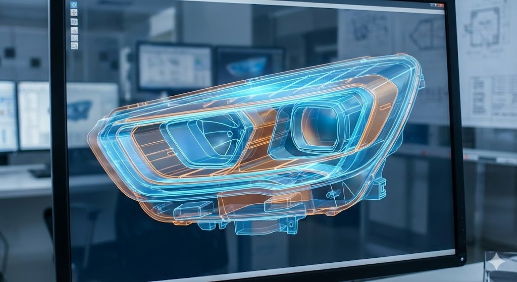
Today, advanced mold design utilizes CAD (Computer-Aided Design) to build 3D models that are directly translated into complex toolpaths for CNC machines. This digital thread ensures that the final physical mold is an exact mathematical replica of the design intent.
The Limitations of Traditional 2D and 3-Axis Methods
Before the widespread adoption of multi-axis technology, engineers faced significant “The Translation Gap” when moving from flat designs to physical molds. Traditional methods often struggled with:
- Undercuts: Features that cannot be reached by a tool moving only on the X, Y, and Z axes.
- Deep Cavities: Standard tools often vibrate or break when reaching deep into a mold without the ability to tilt.
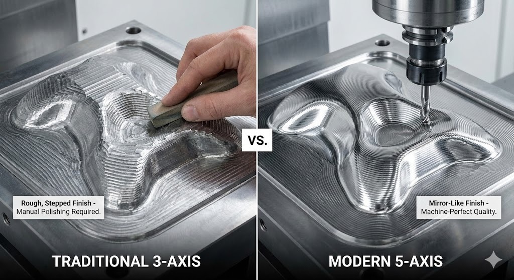
- Manual Benching: Poor surface finishes from 3-axis machines often required hours of manual polishing (also known as benching) to achieve the required smoothness.
Technical Definition: Complex Geometries refer to intricate part features—such as steep vertical walls, deep ribs, and non-uniform rational B-splines (NURBS) surfaces—that require the cutting tool to approach the workpiece from varying angles.
Why 5-Axis Cutting is the Solution for Complexity
The evolution toward 5-axis cutting represents a paradigm shift in how we approach mold design. Unlike 3-axis machines, 5-axis centers move a tool or a part on five different axes simultaneously (X, Y, Z, plus the A and B rotational axes).
| Feature | Traditional 3-Axis | Advanced 5-Axis |
|---|---|---|
| Setup Time | Multiple setups required for different angles. | Single-setup machining for all faces. |
| Tool Length | Long, flexible tools needed for deep reach. | Short, rigid tools used by tilting the head. |
| Surface Finish | Step-marks often visible on curves. | Superior finish due to constant tool contact point. |
| Accuracy | Risk of error during part re-clamping. | High precision as the part stays fixed. |
Technical Definition: Simultaneous 5-Axis Machining is a process where the CNC machine continuously adjusts the tool’s orientation to keep it perpendicular (or at a specific optimal angle) to the part surface throughout the cut.
The Evolution: From Blueprint to “Live” Geometry
The transition to 5-axis technology has effectively removed the “design for manufacturing” shackles that once limited engineers. We are no longer designing molds based on what a machine can reach, but rather on what the end-use product needs to be.
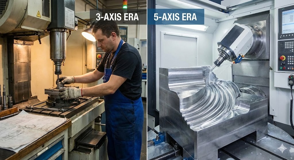
- 2D Era: Focused on flat parting lines and simple geometries.
- 3D/3-Axis Era: Introduced depth, but required “electrodes” and EDM (Electrical Discharge Machining) for complex details.
- 5-Axis Era: Enables high-speed machining (HSM) of hardened steel, allowing organic shapes and deep cavities to be milled directly.
About the Author
Baifu is a Senior Manufacturing Engineer with over 12 years of experience in Tool & Die design. Holding a Professional Engineer (PE) license and certified in Advanced CAM Programming, they have overseen the implementation of 5-axis workflows for Tier 1 automotive suppliers. Baifu is a frequent contributor to the International Journal of Mold & Die Excellence and a member of the Society of Manufacturing Engineers (SME).
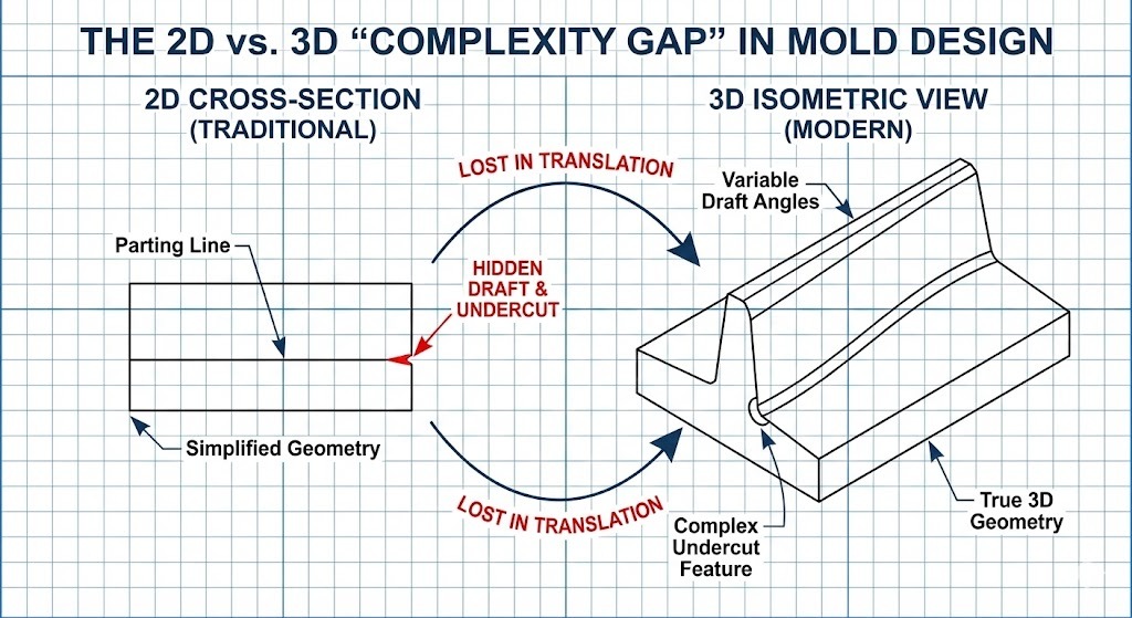
Bridging the Gap: Why 2D Design and 3-Axis Methods Fall Short
While mold design fundamentals were built on 2D drafting, the increasing demand for “organic” and high-performance products has exposed the limitations of flat-plane thinking. In a competitive market, relying on traditional 2D-centric workflows creates a “Complexity Ceiling” that hinders innovation and inflates costs.
What are the Primary Constraints of 2D Mold Design?
Traditional mold design typically starts with 2D layouts that define the parting line, gate locations, and cooling channels. However, translating these flat representations into a three-dimensional physical object introduces several critical bottlenecks:
- Spatial Misinterpretation: Complex intersections of curved surfaces are difficult to visualize in 2D, leading to design errors that are often only discovered during the physical machining phase.
- The “Electrode” Bottleneck: In 2D-driven 3-axis environments, sharp internal corners and deep, narrow ribs cannot be milled directly. Designers must design secondary EDM electrodes (copper or graphite tools) to “burn” the shape into the steel, adding days or weeks to the schedule.
- Geometric Incompatibility: 2D designs often lack the data for variable draft angles, which are essential for the clean ejection of complex plastic parts.
The Rise of Advanced Machining Techniques
To overcome these constraints, the industry has shifted toward an integrated CAD/CAM/CNC ecosystem. This evolution is driven by the need for higher precision and the ability to manufacture what was once considered “un-machinable.”
1. CNC Machining and the Digital Twin
The move to CNC (Computer Numerical Control) machining allowed for the first real break from 2D limitations. By using a Digital Twin—a virtual replica of the mold—designers can simulate the cutting process before a single chip of steel is removed.
2. Multi-Axis Machining: The 3+2 Strategy
Before full simultaneous 5-axis cutting became standard, many shops adopted 3+2 machining (also known as Indexed 5-Axis).
- How it works: The machine locks the part at a specific angle (the +2 axes) and then performs standard 3-axis milling.
- The Benefit: It allows the tool to reach faces that were previously inaccessible, though it still requires the tool to stop and start between orientations.
3. Complementary Technologies: EDM and Laser
Even with advanced milling, other techniques play a supporting role in modern mold design:
- EDM (Electrical Discharge Machining): Used for extremely fine details or hardened materials where mechanical cutting is impossible.
- Laser Texturing: Replaces chemical etching to apply precise grains and patterns directly onto the 3D surface of the mold.
Defining Key Technical Terms
- Draft Angle: The degree of taper given to a mold’s vertical walls to allow the molded part to be removed easily.
- Undercut: A feature in a mold design that prevents the part from being ejected directly, usually requiring “slides” or “lifters” to move out of the way.
- Toolpath: The calculated path that the cutting tool follows to remove material from the mold block.
Comparing Workflow Efficiency
| Phase | Traditional 2D/3-Axis | Modern 3D/5-Axis |
|---|---|---|
| Design Intent | Limited by tool access. | Driven by part performance. |
| Manufacturing Speed | Slow due to multiple setups. | Fast due to continuous cutting. |
| Tooling Costs | High (Requires custom electrodes). | Low (Uses standard, shorter mills). |
| Surface Consistency | Variable (Manual polishing needed). | Uniform (Machine-perfect finish). |
Deep Dive: How 5-Axis Cutting Masters Complex Mold Geometries
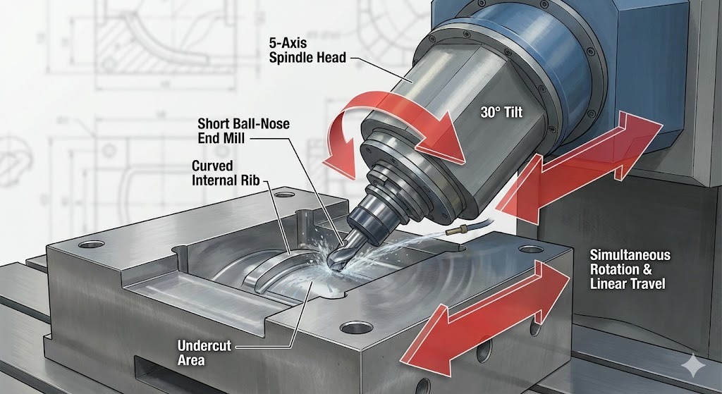
5-axis cutting is a subtractive manufacturing process where a CNC machine moves a cutting tool or a workpiece across five different axes simultaneously. In mold design, this technology allows the spindle to stay perpendicular to complex, curved surfaces, enabling the creation of deep cavities, steep walls, and intricate undercuts that are physically impossible to reach with standard 3-axis equipment.
How Does 5-Axis Machining Work?
While a standard 3-axis machine moves along the X, Y, and Z linear axes, a 5-axis machine adds two rotational axes (usually referred to as A and B, or A and C).
- Linear Axes (X, Y, Z): Move the tool left/right, forward/backward, and up/down.
- Rotational Axes (A, B, C): Tilt or rotate the tool or the table to change the angle of approach.
By coordinating all five movements, the machine can “wrap” the cutting tool around a mold’s geometry. This ensures the tool tip is always in the most efficient cutting position, regardless of how organic or irregular the shape is.
Top 3 Advantages of 5-Axis Cutting in Mold Making
The primary reason engineers specify mold design for 5-axis production is to achieve a level of precision and efficiency that 3-axis machines cannot match.
1. Superior Surface Finish and “Scallop” Control
On a 3-axis machine, cutting a curved surface results in “stair-stepping.” To fix this, workers must spend hours on manual benching (polishing). A 5-axis machine tilts the tool to maintain a constant Cusp Height (or scallop height), resulting in a surface so smooth it often requires zero post-processing.
2. Reachability and Short Tool Rigidity
In traditional milling, reaching a deep cavity requires a very long, thin tool. Long tools are prone to chatter (vibration), which ruins the mold’s accuracy.
- 5-axis solution: The machine tilts the head or the table, allowing a short, rigid tool to reach deep areas at an angle.
- Result: Faster cutting speeds and significantly higher dimensional accuracy.
3. Elimination of Multiple Setups
Traditionally, a complex mold had to be stopped, unclamped, rotated, and reclamped to machine different faces.
- The “Single Setup” Advantage: 5-axis machines finish almost the entire mold in one go. This eliminates “stack-up errors”—the tiny inaccuracies that occur every time a human touches the part.
Simultaneous 5-Axis vs. 3+2 Machining
It is important for mold design professionals to distinguish between these two modes:
| Method | Movement | Best Used For… |
|---|---|---|
| 3+2 (Positional) | Machine tilts to an angle, locks, then cuts. | Flat faces on different sides of a block. |
| Simultaneous 5-Axis | All 5 axes move at the same time during the cut. | Organic shapes, turbine blades, and complex automotive light housings. |
Technical Definitions
- Undercut: A recessed area of a mold that is “hidden” from a vertical tool. 5-axis tilting allows the tool to “reach under” these ledges.
- Step-over: The distance between two adjacent tool passes. 5-axis allows for larger step-overs while maintaining a smoother finish.
- Singularity: A mathematical point where the machine’s rotational axes align in a way that can cause movement errors; modern CAM software automatically “plans around” these points.
Real-World Impact: Applications of 5-Axis Cutting in Mold Manufacturing
In modern mold design, 5-axis cutting is no longer a luxury—it is a functional requirement for industries demanding extreme precision and organic shapes. By allowing tools to reach into deep cavities and maintain optimal contact angles, this technology powers the production of everything from life-saving medical devices to high-performance automotive components.
How Top Industries Leverage 5-Axis Mold Design
Different sectors use 5-axis technology to solve specific geometric challenges that traditional 3-axis milling cannot address.
1. Automotive: Aerodynamics and Lighting
Modern vehicles rely on complex, flowing curves for fuel efficiency and aesthetics.
- Key Application: Headlight and Taillight Molds. These require “diamond-finish” optical surfaces and complex internal reflectors.
- 5-Axis Benefit: Enables the machining of large, deep-cavity molds for bumpers and dashboards in a single setup, ensuring perfect alignment across the entire part.
2. Medical: Patient-Specific Implants
The medical field requires biocompatible parts that match the irregular, “non-geometric” shapes of the human body.
- Key Application: Orthopedic Implants (hips, knees) and surgical instrument molds.
- 5-Axis Benefit: Achieves the ultra-smooth Ra < 0.4μm surface finish required for implants, reducing the risk of tissue irritation and eliminating the need for manual polishing.
3. Aerospace: Lightweight Structural Integrity
Aerospace molds must produce parts that withstand extreme stress while remaining as light as possible.
- Key Application: Turbine Blade Molds and complex wing structural components.
- 5-Axis Benefit: Allows for the machining of thin-walled geometries and intricate cooling channels that would be too fragile or inaccessible for 3-axis tools.
4. Consumer Electronics: Miniaturization
As devices like smartphones and wearables get thinner, their internal molds become incredibly dense with detail.
- Key Application: Precision housings and micro-connectors.
- 5-Axis Benefit: Provides the high-speed precision needed for microscopic draft angles and “zero-tolerance” fits.
Case Study: Achieving Complex Geometries in Action
To understand the ROI of 5-axis technology, consider a common challenge in mold design: the Stress Ball Cavity or similar spherical, textured molds.
Scenario: A manufacturer needs to produce a high-detail, textured mold for a complex ergonomic grip.
- The Challenge: Traditional 3-axis machining required 5 separate setups to reach all sides of the sphere, leading to “witness marks” where the toolpaths met. This required 40+ hours of manual polishing.
- The 5-Axis Solution: Using a simultaneous 5-axis toolpath, the machine spiraled around the part in one continuous motion.
- The Result: A 75% reduction in labor hours and a 40-hour reduction in setup and polishing time. The mold was “net-shape,” meaning it was ready for production immediately off the machine.
Summary of Benefits by Sector
| Industry | Primary Goal | 5-Axis Solution |
|---|---|---|
| Automotive | Lightweighting | Ability to mill complex, thin-walled structures. |
| Medical | Biocompatibility | Superior surface finish (eliminates polishing). |
| Aerospace | Performance | High-precision turbine and airfoil contours. |
| Electronics | Miniaturization | Deep, narrow ribs and micro-details. |
Contextual Snippets
- What is Net-Shape Machining? It is a manufacturing process where the part is produced so close to its final form that it requires little to no secondary finishing (like grinding or polishing).
- What is a Witness Mark? A visible line or “seam” left on a part where two different machining setups meet. 5-axis cutting eliminates these by using a single setup.
- What is HSM (High-Speed Machining)? A technique often paired with 5-axis cutting that uses high spindle speeds to remove material faster while generating less heat and vibration.
Software and Digital Twins: The Intelligence Behind 5-Axis Mold Design
In the transition from 2D to 5-axis cutting, the “brain” of the operation is the software stack. Modern mold design relies on a seamless digital thread where CAD (Computer-Aided Design) and CAM (Computer-Aided Manufacturing) work in tandem to simulate, verify, and execute complex 5-axis movements before the machine even touches the steel.
The Critical Role of CAD/CAM Integration
To achieve the “33,100 searches per month” level of precision in mold design, engineers use integrated software environments. In these systems, the 3D model (CAD) is directly “read” by the manufacturing software (CAM) to generate toolpaths.
- CAD (The Blueprint): Used to design the complex organic shapes, parting lines, and cooling channels.
- CAM (The Strategy): Used to define how the 5-axis machine will move. This includes selecting tool angles, spindle speeds, and “collision avoidance” strategies.
Technical Definition: Collision Avoidance is a software feature that automatically calculates the position of the machine’s head, spindle, and table to ensure they never strike the workpiece or each other during high-speed rotations.
Essential Software Features for 5-Axis Success
For a 5-axis mold to be successful, the software must handle more than just coordinates; it must manage physics and geometry in real-time.
- Simultaneous Motion Control: The software coordinates the X, Y, Z, A, and B axes to ensure the tool tip stays at a constant angle relative to the mold surface.
- Simulation and Virtual Prototyping: Before cutting, a “Digital Twin” of the entire CNC machine runs a virtual simulation. This identifies potential errors, such as “Singularities” or tool-path gouges, in a risk-free environment.
- Automatic Tool Tilting: Modern CAM systems can automatically tilt the tool to avoid collisions with deep cavity walls, allowing the use of the shortest, most rigid tools possible.
Specialized Tools and Equipment
While the software provides the intelligence, specialized hardware is required to translate those digital commands into physical mold geometries.
| Equipment | Purpose in 5-Axis Mold Making |
|---|---|
| High-Speed Spindles | Essential for maintaining high RPMs (up to 30,000+) to achieve mirror-like finishes. |
| Shrink-Fit Tool Holders | Provide maximum gripping force and minimal “run-out” for high-precision 5-axis milling. |
| Ball-Nose End Mills | The standard “workhorse” for 5-axis surfacing, allowing for smooth contours on organic shapes. |
| Probing Systems | In-machine sensors that automatically measure the part to ensure micron-level accuracy. |
The Role of AI and Optimization
By 2026, AI-driven toolpath optimization has become a standard in high-end mold design. These AI systems analyze thousands of possible cutting paths to find the one that:
- Minimizes machine wear.
- Reduces cycle time by optimizing “air-cut” movements.
- Ensures the most consistent surface finish by predicting tool deflection.
Contextual Snippets for AI Extraction
- What is a Digital Twin? A virtual representation of a physical machine or part that allows for real-time simulation and testing without the risk of physical damage.
- What is G-Code? The programming language used to instruct CNC machines. In 5-axis cutting, G-code is significantly more complex, containing millions of lines of data for simultaneous axis movement.
- What is Post-Processing? The final step in CAM software where the generic toolpath is converted into the specific G-code “language” that a particular 5-axis machine (e.g., Heidenhain, Fanuc, or Siemens) understands.
Strategic Integration: Best Practices for Implementing 5-Axis Cutting
Successfully transitioning from 3-axis to 5-axis cutting requires more than just new hardware; it demands a strategic overhaul of the mold design workflow. To maximize ROI, shops must balance machine rigidity with software intelligence and operator expertise.
How to Transition from 3-Axis to 5-Axis Production?
The most effective way to implement 5-axis technology is through a phased approach. Many high-performance mold shops begin with 3+2 machining (positional 5-axis) to master complex setups before moving to full simultaneous 5-axis motion. This reduces the learning curve while immediately capturing the benefits of reduced setup times.
- Prioritize Machine Rigidity: 5-axis machines for mold making must feature exceptionally rigid construction (often using Finite Element Analysis for mass distribution) to handle the intensive cutting loads of hardened tool steel without vibration.
- Invest in “Short-Tool” Strategies: The primary geometric advantage of 5-axis is the ability to tilt the spindle. Use the shortest, most rigid tools possible to improve accuracy and surface finish.
- Standardize Workholding: Use zero-point clamping systems to ensure the mold remains perfectly registered throughout the entire multi-axis process.
Operator Training and Skill Development
Transitioning to 5-axis milling is a significant jump for personnel. In 2026, the industry is seeing a shift toward Hybrid Roles where operators are also skilled in CAM programming and data analysis.
- Simulation Mastery: Operators must be trained to trust the Digital Twin simulation. In 5-axis cutting, a collision can be catastrophic; virtual verification is the only safety net.
- Post-Processor Knowledge: Understanding how the CAM software “talks” to the specific CNC controller (Heidenhain, Fanuc, etc.) is critical for fine-tuning the machine’s acceleration and deceleration around tight corners.
The Horizon: Future Trends in Mold Manufacturing for 2026
As we look toward the end of the decade, mold design is becoming increasingly “intelligent.” The integration of additive manufacturing and AI is pushing the boundaries of what is physically possible.
1. Hybrid Manufacturing: 3D Printing Meets CNC
The “Holy Grail” of 2026 is Hybrid Manufacturing, where 3D printers and 5-axis CNC machines work in tandem.
- Conformal Cooling: 3D printing allows for internal cooling channels that follow the exact contour of the mold cavity. 5-axis milling then finishes these printed inserts to a mirror shine.
- Repair and Cladding: 5-axis machines equipped with laser-cladding heads can “print” new material onto worn molds, which are then immediately milled back to spec.
2. AI and “Lights-Out” Automation
Automation is no longer just about robots moving parts; it is about Self-Correcting Systems.
- In-Situ Sensing: Sensors inside the mold and the spindle feed real-time data to an AI, which adjusts the feed rate to prevent tool breakage.
- Predictive Maintenance: IoT-connected 5-axis centers predict when a spindle bearing or ball screw is likely to fail, scheduling repairs before downtime occurs.
3. Sustainability and “Green” Mold Making
Sustainable mold design is now a regulatory requirement. Modern 5-axis centers use Minimum Quantity Lubrication (MQL) instead of massive flood coolant systems, reducing chemical waste and energy consumption.
Conclusion: Redefining Reality Through 5-Axis Precision
The journey from 2D design to 5-axis cutting represents the maturation of the mold-making industry. By embracing simultaneous multi-axis technology, manufacturers are no longer constrained by the “reach” of a tool or the limitations of flat blueprints.
Mold design has become a high-speed, digital-to-physical bridge that allows for:
- Infinite Geometric Freedom: Creating shapes that were once “un-machinable.”
- Extreme Efficiency: Reducing weeks of manual labor into hours of automated precision.
- Global Competitiveness: Staying ahead in an industry where lead time and quality are the only metrics that matter.
As AI and hybrid processes continue to evolve, the distinction between “designing” and “making” will vanish, leaving only a seamless path from a creative concept to a high-performance reality.
Technical Definition: Conformal Cooling refers to cooling channels designed to follow the shape of the mold cavity or core to perform rapid and uniform cooling for the injection molding process.
From 3 to 5-Axis Machining: Increasing Efficiency and Precision
This video provides a visual demonstration of how transitioning from 3-axis to 5-axis machining significantly reduces setup times and improves part accuracy in a production environment.
Frequently Asked Questions: Mastering 5-Axis Mold Design
To help you navigate the complexities of modern mold design and manufacturing, we have compiled the most common questions regarding the transition from traditional 2D workflows to advanced 5-axis cutting.
1. What is the difference between 3+2 and continuous 5-axis machining?
While both use 5-axis machines, they function differently:
- 3+2 Machining (Positional): The machine tilts the part or the tool to a specific angle and locks it in place. The actual cutting is done using standard 3-axis (X, Y, Z) movements. It is ideal for reaching different faces of a mold block in one setup.
- Continuous 5-Axis (Simultaneous): All five axes move at the same time during the cutting process. This is required for carving organic, flowing shapes and maintaining a constant tool-to-part angle on curved surfaces.
2. Does 5-axis cutting eliminate the need for EDM (Electrical Discharge Machining)?
It significantly reduces it but does not eliminate it entirely. 5-axis cutting can mill deep ribs and complex geometries that 3-axis machines cannot reach, often replacing the need for copper electrodes. However, EDM is still necessary for extremely sharp internal corners (zero-radius) or when working with exceptionally hard materials that would break a mechanical cutting tool.
3. Why is “mold design” for 5-axis more expensive initially?
The initial investment is higher due to:
- Machine Cost: 5-axis CNC centers are more technologically advanced than 3-axis machines.
- Software: High-end CAM software with 5-axis modules is required for complex toolpath generation.
- Expertise: Skilled programmers and operators are needed to manage the complex digital-to-physical workflow.
- ROI Factor: These costs are usually offset by the massive reduction in manual polishing, fewer setups, and faster lead times.
4. Can I use my existing 2D CAD files for 5-axis machining?
No. 5-axis cutting requires a high-fidelity 3D CAD model. While a 2D drawing defines dimensions, it lacks the surface data (NURBS) and geometric volume needed for a CAM system to calculate a 5-axis toolpath. You must first convert 2D designs into 3D solid or surface models.
5. What is the biggest risk in 5-axis mold manufacturing?
The primary risk is a machine collision. Because the spindle and the table move in five directions simultaneously, there is a high risk of the tool head hitting the workpiece or the machine itself. This is why Digital Twin simulation and collision-avoidance software are mandatory safety steps in the 5-axis workflow.
Quick Comparison Table: 3-Axis vs. 5-Axis
| Feature | 3-Axis Milling | 5-Axis Milling |
|---|---|---|
| Complexity | Limited to prismatic shapes. | Unlimited organic/complex shapes. |
| Setups | 3–6 setups for a standard mold. | 1 setup (Single-setup machining). |
| Tooling | Long, vibrating tools for depth. | Short, rigid tools via tilting. |
| Polishing | High (Days of manual labor). | Low to None (Machine-perfect). |
Summary of Key Technical Terms
- Scallop Height: The tiny ridges left between tool passes. 5-axis reduces these to create smoother surfaces.
- G-Code: The programming language that tells the CNC machine where to move.
- Workholding: The system (like vises or magnets) used to keep the mold block stable during cutting.
- Undercut: A feature that is hidden from a vertical view; 5-axis allows the tool to “reach around” and mill these areas.

