 English
 Indonesia

An expert guide for design engineers and procurement specialists on optimizing custom molded rubber components, navigating tolerance standards, and streamlining international production.
Design Guidelines for Rubber Injection Molded Parts
Designing elastomeric components requires a distinct engineering mindset compared to rigid thermoplastic molding. Because synthetic rubber undergoes significant cross-linking during vulcanization, flow dynamics and volumetric shrinkage dictate precise geometric constraints. A primary failure mode in custom rubber molding is inconsistent nominal wall thickness, which creates non-uniform cure rates, severe internal voiding, and surface sink marks. Maintaining a recommended wall thickness of 1.5 mm to 5.0 mm (with absolute functional minimums around 0.5 mm for miniature diaphragms) ensures balanced compound flow and thermal equilibrium throughout the cavity.
Corner radii and draft angles directly govern tool longevity and part ejection efficiency. Sharp internal corners concentrate mechanical stress and impede elastomer flow; therefore, internal fillet radii must measure at least 25% of the adjacent nominal wall thickness (minimum 0.5 mm). While the inherent elasticity of low-durometer rubber allows for forced demolding (stripping) of minor undercuts, applying a draft angle of 1.0 to 2.0 degrees per side remains critical for high-durometer compounds (above 70 Shore A) or textured surfaces to prevent tearing during high-speed ejection.
For sealing profiles, custom gasket cross-sections require strict adherence to deformation limits. Under nominal clamp load, elastomeric seals should experience 15% to 30% compression squeeze. Over-designing seal volume relative to the gland cavity causes hydraulic locking and premature compression set failure.
| Design Parameter | Recommended Target | RMA Class A2 (High Precision) | ISO 3302-1 Class M2 |
|---|---|---|---|
| Nominal Wall Thickness | 1.5 mm to 5.0 mm | +/- 0.10 mm (for dimensions < 10 mm) | +/- 0.16 mm (for dimensions < 10 mm) |
| Internal Fillet Radius | >= 25% of wall thickness | +/- 0.15 mm (10 to 25 mm) | +/- 0.20 mm (10 to 25 mm) |
| Draft Angle | 1.0 to 2.0 deg per side | +/- 0.20 mm (25 to 50 mm) | +/- 0.32 mm (25 to 50 mm) |
| Undercut Depth | < 5% without mechanical core | +/- 0.25 mm (50 to 80 mm) | +/- 0.40 mm (50 to 80 mm) |
Table 1: Key design parameters and comparison between RMA Class A2 Precision and ISO 3302-1 Class M2 molding standards.
Material Selection: Silicone, EPDM, and Specialty Elastomers
Selecting the optimal elastomer compound requires aligning chemical polymer structures with operating environment demands. Cross-linking density achieved during vulcanization directly influences physical properties, including tensile strength, durometer hardness (Shore A), and compression set resistance. Compression set represents the permanent deformation remaining after a compressing force is released. Compression set percentage is expressed mathematically as C = [(t0 - t1) / (t0 - tn)] * 100, where t0 is the original specimen thickness, t1 is the final specimen thickness after recovery, and tn is the spacer bar height.
Silicone Rubber (VMQ / Liquid Silicone Rubber - LSR) features a inorganic silicon-oxygen backbone that exhibits thermal stability from -60 degrees C to +230 degrees C. LSR provides extreme bio-compatibility and low compression set, making it the premier choice for medical and food-contact applications. Ethylene Propylene Diene Monomer (EPDM) utilizes a non-polar hydrocarbon backbone, offering outstanding resistance to ozone, polar solvents, steam, and outdoor weathering at a significantly lower raw material cost than silicone. Fluorocarbon elastomers (FKM / Viton) utilize carbon-fluorine bonds to deliver superior fluid resistance against aggressive aromatic hydrocarbons, synthetic fuels, and concentrated chemicals up to +250 degrees C.
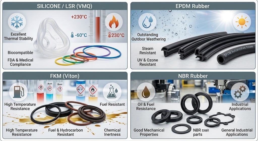
| Elastomer Polymer Type | Hardness Range | Service Temp (deg C) | Tensile Strength | Key Regulatory Compliance |
|---|---|---|---|---|
| Silicone (VMQ / LSR) | 10 to 80 Shore A | -60 to +230 | 5 to 11 MPa | FDA 21 CFR 177.2600, USP Class VI |
| EPDM Rubber | 40 to 90 Shore A | -45 to +150 | 8 to 20 MPa | NSF 61 (Potable Water), Recyclable TPV options |
| Fluoroelastomer (FKM) | 50 to 90 Shore A | -20 to +250 | 10 to 18 MPa | UL94 V-0 flame rating, Automotive OEM specifications |
| Nitrile (NBR) | 30 to 90 Shore A | -30 to +120 | 7 to 18 MPa | Commercial fuel/oil exposure standards |
Compliance mandates in North American markets dictate compound formulation rigor. Products intended for repeated contact with food must use ingredients listed under FDA 21 CFR 177.2600. Healthcare components require USP Class VI biological reactivity testing, verifying non-toxicity under systemic and intracutaneous evaluations. Drinking water distribution parts require NSF 61 certification to ensure zero toxic leachables under ambient and elevated hot-water exposure.
The Injection Molding Process, Tooling, and Quality Assurance
Rubber injection molding differs fundamentally from thermoplastic processing regarding barrel thermal management. Rubber compounds are plasticized inside a temperature-controlled barrel at 70 to 90 degrees C to maintain fluid viscosity without triggering premature cross-linking (scorch). High injection pressure (1000 to 2000 bar) forces the homogeneous preheated rubber into a heated mold cavity (160 to 200 degrees C). The thermal energy inside the cavity initiates rapid vulcanization, transforming the fluid polymer into an elastic solid matrix before part ejection.
Process Architecture Comparison: Injection vs. Compression vs. Transfer
- Injection Molding: Fully automated, closed-cavity filling. Rapid cycle times (30 to 120 seconds). Ideal for high-volume, complex geometries requiring RMA Class A2 tolerances. High initial tooling investment.
- Transfer Molding: Semi-automated, intermediate precision. Piston forces pre-measured perform from a pot into closed mold cavities. Lower tooling cost than injection; suitable for low-to-medium volumes and metal insert overmolding.
- Compression Molding: Manual preform loading into open cavity. Longer cycle times (3 to 10 minutes). Low tooling investment; best suited for large-format gaskets, low-volume runs, and ultra-high durometer compounds.
Quality control protocols leverage the standardized ASTM D2000 callout system. A typical material callout such as ASTM D2000 M2BG714 B14 EA14 defines polymer family (BG = NBR), durometer hardness (70 +/- 5 Shore A), minimum tensile strength (14 MPa), and specific test requirement suffixes for compression set (B14) and fluid resistance (EA14).
| Molding Defect | Root Cause Analysis | Preventive Design / Process Solution |
|---|---|---|
| Excessive Flash | Insufficient clamp force; worn parting lines; excessive injection pressure | Increase clamp tonnage; redesign parting lines; apply cryogenic deflashing post-processing |
| Short Shot (Underfill) | Premature cure (scorch); trapped air; insufficient shot volume | Incorporate micro-vents (0.02 mm depth); lower barrel temperature; optimize runner size |
| Porosity / Blistering | Trapped volatiles or moisture in compound; incomplete vulcanization | Implement vacuum-assisted molding systems; extend cure dwell time; pre-dry raw materials |
| Flow Marks / Knit Lines | Low melt temperature; poor merging of flow fronts across cores | Increase injection velocity; elevate mold surface temperature; relocate gate positions |
Cost Drivers, Prototyping, and Partner Selection
Unit economics in custom rubber molding depend on amortized tooling expenses, raw material mass, cycle time, and post-processing requirements. The mathematical cost model per part is represented as Unit Cost = (Tooling Cost / Total Production Volume) + Material Cost + [(Machine Hourly Rate * Cycle Time) / Cavity Count] + Post-Processing Cost.
Tooling costs vary based on cavity count, steel grade (e.g., P20 vs. hardened NAK80/H13), and runner system design. A single-cavity prototype mold typically costs between $2,500 and $6,000 with a lead time of 2 to 3 weeks. Production multi-cavity hardened steel tooling (8 to 32 cavities) ranges from $12,000 to $45,000, requiring 4 to 6 weeks for fabrication, T1 sampling, and CMM dimension verification.
For low-volume production (500 to 5,000 units), aluminum soft tooling or 3D-printed mold inserts (using high-temperature photopolymer resins) provide a cost-effective bridging solution. While rapid prototyping accelerates validation, engineers must account for minor material property discrepancies between prototype additive resins and final injection-molded production compounds.
Manufacturing Partner Assessment Framework
When evaluating international vs. nearshore manufacturing partners, procurement teams should audit suppliers against key quality and engineering milestones:
- Quality System Certifications: ISO 9001 (General Quality), IATF 16949 (Automotive), or ISO 13485 (Medical Devices).
- In-House DFM & Simulation: Advanced mold-flow analysis capabilities to predict air traps, fill balance, and volumetric shrinkage prior to cutting steel.
- Advanced Overmolding Expertise: Demonstrated experience in multi-shot or insert overmolding (bonding rubber directly to metal or plastic substrates using chemical primers).
- Tool Ownership & Guarantee: Full ownership rights transferred to the buyer upon payment, combined with a lifetime tool maintenance guarantee for the active production lifespan.
Accelerate Your Custom Rubber Molding Project
Upload your CAD files today to receive a comprehensive Design for Manufacturability (DFM) review, including tolerance stack-up analysis, compound recommendations, and an instant production quote.
Request DFM Review & QuoteFrequently Asked Questions
What are the most important design rules for custom rubber injection molded parts?
Maintain uniform wall thickness between 1.5 mm and 5.0 mm, specify internal fillet radii equal to at least 25% of the wall thickness, apply 1.0 to 2.0 degree draft angles per side, and design parts to align with standard RMA Class A2 precision tolerances.
How do I choose between silicone and EPDM for my rubber molding project?
Select Silicone (VMQ/LSR) for extreme temperatures (-60 to +230 degrees C), biological compatibility, FDA/USP compliance, or low compression set requirements. Choose EPDM for cost-effective outdoor applications requiring high resistance to ozone, weather, steam, and polar fluids.
What is the typical cost per part for rubber injection molding, and what factors influence it?
Unit cost depends on material selection, part volume, cure time, cavity count, and deflashing method. High-cavitation tooling dramatically reduces per-part labor and machine time expenses over large production volumes.
How long does it take to build injection mold tooling for rubber parts?
Prototype or soft tooling typically requires 2 to 3 weeks. Production multi-cavity steel molds generally require 4 to 6 weeks, including tool design, CNC machining, EDM processing, and initial T1 sample validation.
What are common defects in rubber injection molding and how can I prevent them?
Common defects include flash (mitigated by precise parting lines and cryogenic deflashing), short shots (prevented by vacuum venting and scorch management), and internal porosity (controlled via vacuum-assisted molding and optimized cure cycles).
What FDA or medical-grade requirements apply to rubber parts in the US?
Food-contact parts require compliance with FDA 21 CFR 177.2600. Medical-grade components require USP Class VI biological evaluation testing, while drinking water components mandate NSF 61 certification.
How does injection molding compare to compression or transfer molding for rubber components?
Injection molding delivers superior dimensional precision, automated consistency, and rapid cycle times for high volumes. Transfer molding is cost-effective for medium volumes and insert bonding, while compression molding offers the lowest initial tooling costs for low-volume or large-format parts.


